New South Wales
Sydney
02 8708 4400
Victoria
Melbourne
03 8773 5300
Queensland
Brisbane
07 3442 6200
Western Austalia
Perth
02 8708 4400
www.
acprod
.com.au
ACP
|
April
2016 |
Page
14
Product & Installation: ABSORB
®
350 Non-Redirective Gating Crash Cushion
Step 2
Continue attaching, alternating Type “A” and
Type “B” Energy Absorbing Cartridges by
repeating Step 1, until the desired system length
is reached.
Important note:
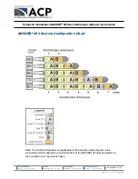
On 70 kmph and higher systems some elements
require two vent/fill holes. Refer to the system
configuration chart to determine which elements
require two vent/fill holes. If the elements are not
shipped with two holes, the second hole must
be cut in these elements. Cut the second hole on
the top of the other end of the element following
the hole layout of the existing hole.
(Follow the element orientation exactly as
shown in the configuration diagram on page
11.) The additional evaporation caps for the
new holes are shipped in the nose piece box.
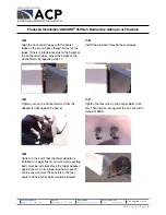
Step 3
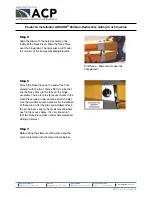
Four tabs connect the final Energy Absorbing
Element to the nose piece. These tabs are the
mounting points for the nosepiece. The hardware
is packed in the nose piece box.
Step 4
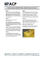
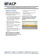
Attach the tabs as shown in the picture above.
Before tightening the bolts, align the tabs so that
a pin can be inserted from the top, through both
of the holes. The upper tabs attach to the bottom
side of the top hinge flange and the lower tabs
attach to the top side of the bottom flange.

