-
-
11
1.4.3
Main Circuit
(1)
Main circuit wiring
Connect wiring as shown in Fig.1.4
BRAKING RESISTOR
(OPTION)
Fig.1.4 Main Circuit Wiring
(2)
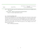
Main circuit terminals
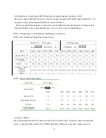
Table 1.1 7200M3 Main Circuit Terminals
Terminal Description
R
S
T
Main circuit power input
R , S are used for single-phase input
specifications.
U
V
W
Inverter output
B1/P
B2
Braking resistor (options)
E*
Grounding (ground resistance should be 100 ohms or less)
* Use screw for frame ground.
•
Main circuit terminal arrangement
3-Phase series (all models) 220V single-phase series
R S T B1/P B2 U V W
R S B1/P B2 U
V
W
BLANK
7200M3
(R)
(S)
(T)
(U)
IM
(V)
(W)
E
MOTOR
1
2
B1/P
B2
P
B
(R)
(S)
(T)
GROUNDING
POWER SUPPLY
Only terminal R,S
For single phase series


