-
-
16
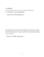
(6) Wiring
(a)Main circuit input/output
(1)Phase rotation of input terminals R, S, T is available in either direction, clockwise or
counterclockwise.
(2)When inverter output terminals U, V, W are connected to motor terminals (U, V, W) respectively,
motor rotates counterclockwise, when viewed from opposite drive end, upon forward run
command.To reverse the rotation, interchange any two of the motor leads.
(3)Never connect AC main circuit power supply to output terminals U, V, W. Inverter may be damaged.
(4)Insert an L noise filter to the 7200M3 output, but never connect power factor correction capacitor,
LC or RC to 7200M3 output.
(5) Be sure to tighten the main circuit terminal screws.
(6) Be sure to separate the main circuit wiring from inverter and peripheral device control
lines.Otherwise, it may cause the devices to malfunction.
(b)Grounding
(1)Ground the casing of the 7200M3 using ground terminal E. Ground resistance should be 100ohm or
less.
(2)Never ground 7200M3 in common with welding machines, motors, or other large-current electrical
equipment,or a ground pole. Run the ground lead in a conduit separate from leads for
large-current electrical equipment.
(3)Use the ground leads which comply with A WG standards and make the length as short as possible.
(4)Where several 7200M3 units are used side by side, all the units should be grounded as shown in (a)
or (b) of Fig 1.5. Do not from a loop with the groundleads as shown in (c).
(a) GOOD (b) GOOD (c) POOR
Fig.1.5 Grounding of Three 7200M3 Unit


