-
-
22
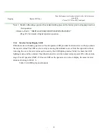
Fig. 1.9 shows the output voltage for
inverter output frequency. When its
characteristic (max.voltage/frequency)
differs from that of the optimum motor,
refer to “V/f CHARACTERISTIC
SETTING” on page 69.
*For 440 V class, the value is twice that
of 220 V class.
Fig. 1.9 V/f Characteristics
Since the inverter is provided with an
electronic thermal overload protective
function in order to protect the motor from
overheating, set the rated current value
described on the motor nameplate to
constant (Pn-19). TECO standard 4-pole
motor current value is set as the initial
value .For details, refer to “ELECTRONIG
THERMAL OVERLOAD FUNCTION”
on page 74.
Note:
Provide a thermal overload relay or
thermal protector for each motor when
more than two motors are operated
simultaneously.
V / F characteristics
Motor rated current
setting
220 (V)
(Hz)
0 1.5 3 50 60
14
8
○
2
○
1
○
F

