background image

Multi Variable Air Conditioners WALL Mounted Type Indoor Unit 

2.2 Rated Operating Condition 

Item 

  Indoor Side Condition 

  Outdoor Side Condition 

Dry Bulb Temp


(°F) 

Wet Bulb Temp 


(°F) 

Dry Bulb Temp 


(°F) 

Wet Bulb Temp 


(°F) 

Rated Cooling 

27(80.6) 

19(66.2) 

35(95) 

24(75.2) 

Rated Heating 

20(68.0) 

15(59.0) 

7(44.6) 

6(42.8) 

Indoor Unit Working Temperature Range:16°C(60.8 °F)~32°C(89.6 °F). 

3Installation Instruction 

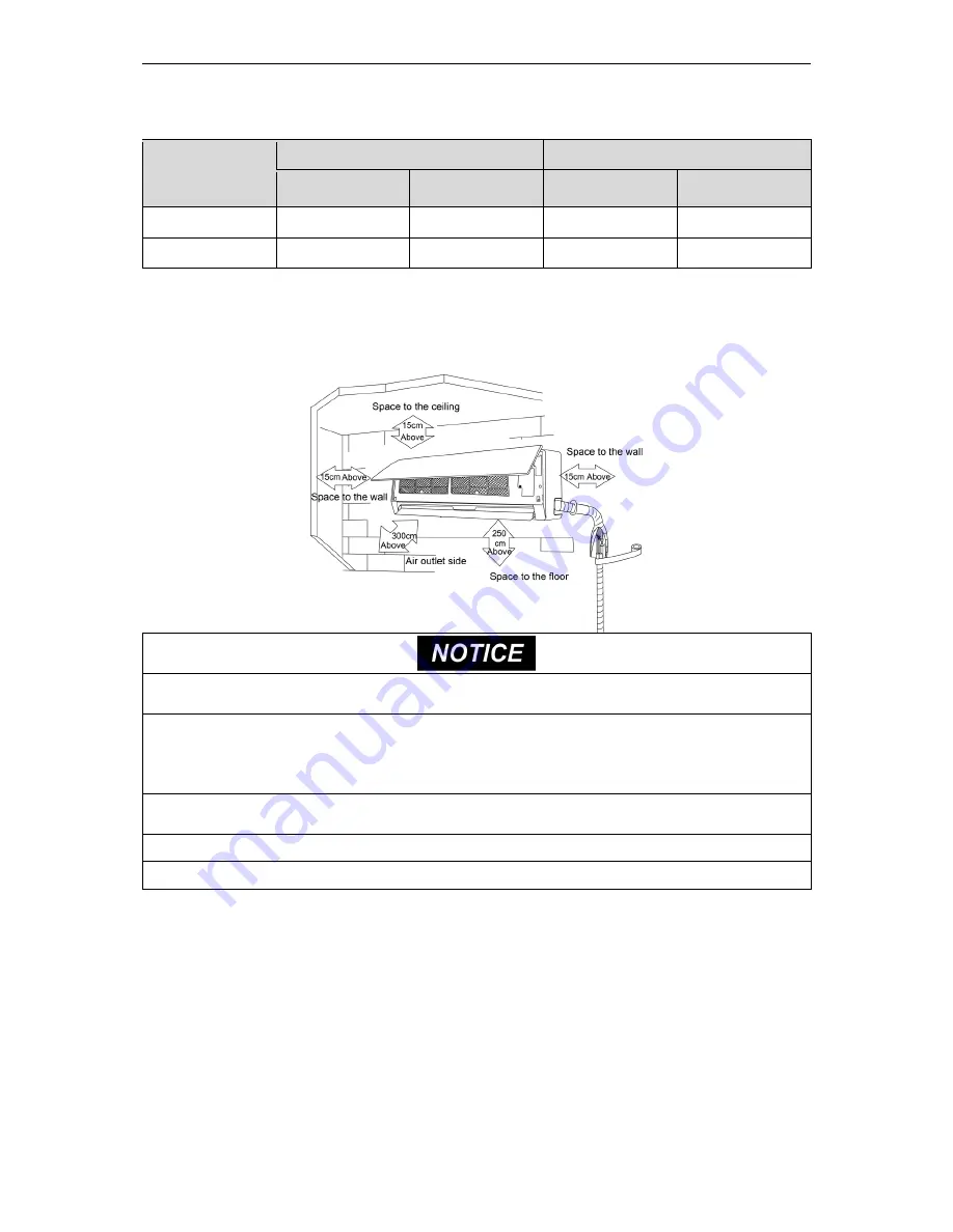
3.1 Schematic diagram of installation spaces 


(1)


The    unit    shall    be    installed    by    the    professional    personnel    according    to    this   

installation instruction to ensure proper use. 

(2)


Please contact the local AC PRO appointed service center before installation. Any malfunctioncaused by the 

unit that is not installed by the AC PRO appointed service center would probably not be dealt with on time 

because of the inconvenience of the business contact. 

(3)


It should be guided under the professional personnel when the air conditioner unit is moved to other 

place. 

(4)


The appliance shall not be installed in the laundry. 

(5)


The indoor unit should be installed at 2.3m or higher above the floor. 

3.2 Requirements for Communication Line 

NOTICE

!  If  the  unit  is  installed  in  the  place  with  strong  electromagnetic  interference, 

shielded wire must be applied on the communication wire between indoor unit and wired 

controller. Twisted pair line with shielding function must be applied on the communication 

wire between indoor unit and indoor unit(outdoor unit). 


3.2.1 Select communication line for indoor unit and wired controller 

Summary of Contents for GMV-N07G/A3A-D

Page 1: ...al carefully before operation and retain it for future reference Multi Variable Air Conditioners Wall Mounted Type Indoor Unit Models GMV N07G A3A D U GMV N07G E3A D U GMV N09G A3A D U GMV N09G E3A D U GMV N12G A3A D U GMV N12G E3A D U GMV N18G A3A D U GMV N18G E3A D U GMV N24G A3A D U GMV N24G E3A D U ...

Page 2: ......

Page 3: ...ners should well keep this manual 6 If this unit fails to operate normally please contact our service center as soon as possible and provide the following information 1 Content on the name plate model number cooling capacity production code ex factory date 2 Malfunction details before and after the malfunction occurs 7 Each unit has been strictly tested and proved to be qualified before ex factory...

Page 4: ......

Page 5: ... Connect Cables and Terminals of Wiring Board 7 5 2 Power Cord Connection 8 5 3 Connection of Communication Line of IDU and ODU 8 5 4 Connection of Communication Line of Wired Controller 9 5 5 Illuminate for Connection of Wired Controller and Indoor Units Network 9 5 6 Installation of the indoor unit 9 6 The Best Usage Method 10 7 Maintenance Method 11 7 1 Cleaning panel 11 7 2 Cleaning the air fi...

Page 6: ...uipment is used 10 Never start up or shut off the air conditioner by means of directly plug or unplug the power cord 11 Turn off the unit after it runs at least five minutes otherwise it will influence oil return of the compressor 12 Do not allow children operate this unit 13 Do not operate this unit with wet hands 14 Turn off the unit or cut off the power supply before cleaning the unit otherwise...

Page 7: ...al happens such as burning smell please power off the unit and cut off the main power supply and then immerdiately contact AC PRO appointed service center If abnormality keeps going the unit might be damaged and lead to electric shock or fire 27 Turn off the unit after it runs at least five minutes otherwise it will influence oil return of the compressor 28 Under the standby status the unit will c...

Page 8: ...functioncaused by the unit that is not installed by the AC PRO appointed service center would probably not be dealt with on time because of the inconvenience of the business contact 3 It should be guided under the professional personnel when the air conditioner unit is moved to other place 4 The appliance shall not be installed in the laundry 5 The indoor unit should be installed at 2 3m or higher...

Page 9: ... outdoor unit Fig 3 2 2 Material Type Total Length L m feet of Communication Cable between Indoor Unit and Indoor Outdoor Unit Wire size mm2 AWG Materi al Standa rd Remarks Light Ordinary polyvinyl chloride sheathed cord 60227 IEC 52 60227 IEC 53 L 1000m L 3280 5 6feet 2 0 75 2 AWG18 IEC 60227 5 2007 1 If the wire diameter is enlarged to 2 1 mm 2 2 AWG16 the total communication line length can rea...

Page 10: ...of power cord and air switch provided by manufacturer 4 Install cut off device near the unit The minimum distance between each stage of cut off device should be 3mm 1 8 inch The same for both indoor unit and outdoor unit 5 If the supply cord is damaged it must be replaced by the manufacturer or its service agent or a similarly qualified person in order to avoid a hazard 4 Installation Instructions...

Page 11: ...door unit automatically Then you can reset the master indoor unit by remote controller or wired controller 4 3 1 Setting by remote controller Point the remote controller at the light board or wired controller In fan mode set master mode indoor unit through and button 1 Adjust set temperature to 30 2 Within 5 seconds press button and then press button repeatedly for three times After finishing sett...

Page 12: ...y out the wiring work incorrect wiring could cause malfunction or even damage the unit 3 The unit should be powered by independent circuit and specific socket 4 The wiring should be in accordance with related regulations in order to ensure the units reliable running 5 Install circuit breaker for branch circuit according to related regulations and electrical standards 6 Keep cable away from refrige...

Page 13: ... for tightening the terminal Fig 5 1 1 Fig 5 1 2 5 2 Power Cord Connection NOTICE All indoor units must be unified of power supply so that they can be powered ON OFF at the same time Fig 5 2 For units with single phase power supply 1 Detach the electric box lid 2 Let the power cord pass through the wiring through holes 3 Connect the power cord to terminal L N 4 Fix the power card with wiring clamp...

Page 14: ... Controller and Indoor Units Network 1 Communication wire of indoor unit and outdoor unit or indoor unit is connected to D1 D2 2 Wired controller is connected to H1 H2 3 One indoor unit can connect two wired controllers that must be set as master one and slave one 4 One wired controller can control 16 indoor unitS in maximum at the same time 1 The type of indoor units must be the same if they are ...

Page 15: ...properly in proper to prevent electricity wasting It is better tocontrol the difference of the indoor and outdoor temperatures within 5 C 41 F 2 The better effect will be maintained by adjusting the guide louver downward for heating and horizontal for cooling 3 When the air conditioner is running don t open windows or doors for long time otherwise the efficiency of unit will be lowered 4 Prevent t...

Page 16: ...rows to take down the panel 2 Clean the panel Clean it with a soft hair brush water and neutral cleaning fluid and then dry it 3 Install the panel As shown in Fig II install the stands of both ends of the panel into the slot and put the middle rotating shaft into the groove then place the panel and clasp back along the arrow direction Fig 7 1 1 Fig 7 1 2 7 2 Cleaning the air filters Clean it once ...

Page 17: ...ge season 1 Clean filter and body of air conditioner 2 Cut off the main power supply of air conditioner 8 Table of Error Codes for Indoor Unit Error Code Content Error Code Content Error Code Content L0 Indoor Unit Error L9 Quantity Of Group Control Indoor Units Setting Error d8 Water Temperature Sensor Error L1 Indoor Fan Protection LA Indoor Units Incompatibility Error d9 Jumper Cap Error L2 E h...

Page 18: ... If TIMER had been set on the wireless remote controller The cooling heating effect of the air conditioner was not good Is the temperature set properly Is the inlet outlet vent of the outdoor unit blocked Is the air filter too dirty to cause blockage Are windows and doors closed Is the air speed too low Is there other heat source in the room The wireless remote controller cannot work In the event ...

Page 19: ...ote controller can make the guide louver swing up and down or makes the guide louver stop at a certain angle to have air supplied 2 Press the SWING button on the wireless remote controller to make the guide louver swing up and down Repress again to stop the operation 10 2 Adjusting air direction left and right Moving the vertical louver left and right can adjust the left and right direction of air...

Page 20: ...0DWHULDO 6XSSO QF GED 3UR Add 11700 Industry Ave Fontana CA 92337 USA Tel 1 951 360 0630 E mail www acpro com ...

Reviews: