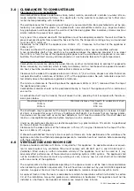
CHECKING THE BURNER AND SPARK GAP
There are no imitation fuel bed components to install. The appliance features a ribbon burner which is
designed to produce a continuous band of flame over it’s length. The burner should be visually inspect-
ed to ensure it is free from any foreign matter.
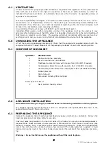
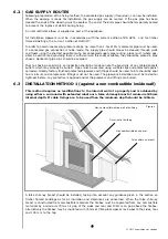
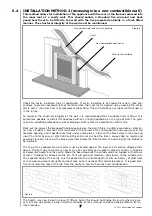
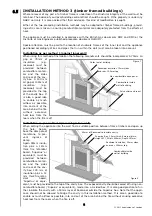
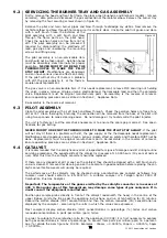
If it is necessary to clean or dust off the burner then (if fitted) the
glass door should be removed by removal of the four retaining
screws. Re-fit the glass door after cleaning or inspection, ensur-
ing a good seal.
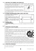
The gap between the spark electrode and the pilot should be 3 -
5mm to produce a good spark. There should be no need to adjust
this. If under any circumstances the piezo electric spark fails, the
pilot cannot be lit manually.
FITTING THE DECORATIVE FRAME, FRONT AND HOOD
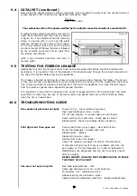
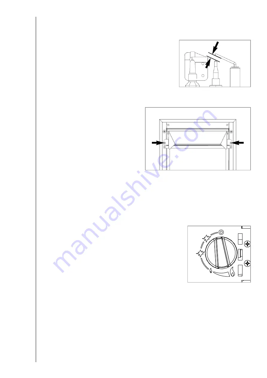
The appliance is supplied with a decorative
frame and hood. Attach the hood using two M6
screws as shown in figure 13.
Remove all protective film from the frame. The
frame is retained by four magnets on the front
face of the firebox. Position the frame onto the
magnets.
IMPORTANT : Due to the possibility of sharp
edges, care should be taken when handling the
frame. The use of protective gloves is recom-
mended.
TESTING AND
COMMISSIONING
Turn on and test the gas supply up to the fire for any leaks, in accordance with the current edition of
BS6891.
OPERATING THE APPLIANCE
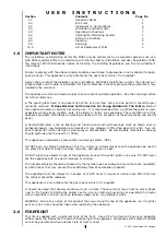
The control knob is supplied in the loose parts pack. Fit the control knob onto the valve spindle as shown
in figure 14.
The pilot is visible behind the left hand side of the burner. Push the control knob in fully and turn anti-
clockwise through both of the SPARK positions, keeping fully
depressed, hold there for a few seconds. If the fire has not been used
for some time, hold the knob in this position for longer, to allow any
air in the pipes to be purged.
Continue turning anti-clockwise through the spark clicks to the nine
o’clock position, ensuring the pilot has lit. If not, return the knob
clockwise, and repeat.
When the pilot lights after one of the two sparks, keep the knob
depressed in the nine o’clock position for approximately ten seconds.
Now release the knob and the pilot should stay alight. If the pilot is
extinguished during use, wait three minutes before repeating the ignition procedure.
To achieve the HIGH setting, push the control knob in slightly and continue turning anti-clockwise to
the high position. The main burner should light after a few seconds. To decrease the setting to LOW,
push the knob in slightly and turn the control knob clockwise to the low setting. To turn to the pilot only
position from the HIGH or LOW positions, press the control knob in, and return to the nine o’clock posi-
tion and release. To turn the fire OFF, keep the knob pressed in, return to the off position and release.
OPERATING PRESSURE
The pressure test point is located on the inlet restrictor elbow. Release the pressure test point screw,
and attach a pressure gauge.
10
7.2
Figure 12
Spark gap
©
2011 Acquisitions of London
Figure 13
7.3
8.0
8.1
8.2
Figure 14


