background image


TABLE OF CONTENTS


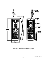
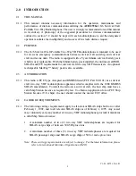
FIGURE 1:  ACR/GMDSS 16/6 SURVIVAL RADIO

.................................................... 1 

 
1.0 TECHNICAL 

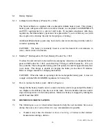
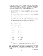
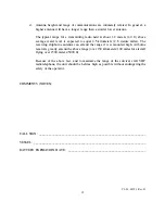
SPECIFICATIONS................................................................ 2 

 
2.0 INTRODUCTION ................................................................................... 3 

2.1 This 

Manual.................................................................................. 3 

2.2 Purpose ....................................................................................... 3 
2.3 Authorization ............................................................................... 3 
2.4 Carriage 

Requirements..................................................................... 3 

 
3.0 OPERATING 

CONTROLS AND INDICATORS ............................................. 4 

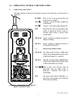
FIGURE 2:  ACR/16/6 GMDSS CONTROL PANEL

........................................... 4 

3.1 Operating 

Controls ......................................................................... 4 

3.2 Operating 

Indicators........................................................................ 4 

 
4.0 OPERATION ......................................................................................... 5 

4.1 Channel 

16 

Operation ...................................................................... 5 

4.2 Channel 

Operation ....................................................................... 5 

4.3 Battery 

Save Feature  ...................................................................... 5 

 
5.0 INSTALLATION 

AND MAINTENANCE ...................................................6-8 

5.1 Installation.................................................................................... 6 
5.2 Mandatory 

Testing........................................................................6-7 

5.3 Visual 

Inspection............................................................................ 7 

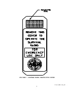
FIGURE 3:  CONTROL PANEL PROTECTIVE COVER

..................................... 8 


6.0 BATTERY 

INFORMATION .................................................................. 9-10 

FIGURE 4:  BATTERY REPLACEMENT

........................................................ 9 

6.1 Battery 

Options.............................................................................10 

6.1.1  Lithium Survival Battery (Product No. 1066) ...............................10 
6.1.2 MaxCap

Ô

 Rechargeable (Ni-Cad) Battery (Product No. 1067)..........10 

6.2 

How to Replace the Battery Pack .......................................................10 

  
7.0 DISTRESS 

COMMUNICATIONS ..........................................................10-12 


 i 

Summary of Contents for 2726A

Page 1: ...1 Rev B SR 102 Product No 2726A GMDSS 16 6 Survival Radio ACR Electronics Inc 5757 Ravenswood Road Fort Lauderdale Fl 33312 1 954 981 3333 Fax 1 954 983 5087 www acrelectronics com Email Info acrelect...

Page 2: ...rs 4 4 0 OPERATION 5 4 1 Channel 16 Operation 5 4 2 Channel 6 Operation 5 4 3 Battery Save Feature 5 5 0 INSTALLATION AND MAINTENANCE 6 8 5 1 Installation 6 5 2 Mandatory Testing 6 7 5 3 Visual Inspec...

Page 3: ...Y1 03 0079 1 Rev B 1 FIGURE 1 ACR GMDSS 16 6 SURVIVAL RADIO...

Page 4: ...IVER Sensitivity 12dB SINAD 1 0mV Audio Output 300 mW BATTERY Type Primary Lithium Storage Life 10 Years Operating Life under typical 8 hours 20 C duty cycle of 1 9 i e 6 sec Tx 6 sec Rx 48 sec stand...

Page 5: ...l rechargeable MaxCap battery pack is also available 2 3 AUTHORIZATION 2 3 1 This radio is FCC Type Accepted and GMDSS listed FCC Part 80 1101 as a survival craft two way VHF radiotelephone apparatus...

Page 6: ...ly CHAN 16 Selects operation on Marine Channel 16 Distress Calling CHAN 6 Selects operation on Marine Channel 6 Communications USCG 3 2 OPERATING INDICATORS CHAN 16 The push switch includes a RED ligh...

Page 7: ...turn unit off 4 2 CHANNEL 6 OPERATION CHAN 6 a Remove control panel protective cover b Strap the unit around operator s wrist hand or glove c Press ON OFF button for one 1 second to turn on the Survi...

Page 8: ...lized to monitor proper operation of the Survival Radio the test distance between devices should be kept to a maximum and the following message format should be observed name of station transmitting t...

Page 9: ...the test signal was not heard full quieting have the unit inspected at your nearest authorized service center p Have someone return the call from the monitoring station lowest power setting to verify...

Page 10: ...Y1 03 0079 1 Rev B 8 FIGURE 3 CONTROL PANEL PROTECTIVE COVER...

Page 11: ...Y1 03 0079 1 Rev B 9 6 0 BATTERY INFORMATION FIGURE 4 BATTERY REPLACEMENT...

Page 12: ...CR Product No 1067 and a MaxCap Charger ACR Product No 2711 are also available The rechargeable battery pack will operate the unit for approximately four to six hours The charger is capable of chargin...

Page 13: ...distress call use the two pronunciations above when calling for example also see example for part c M AIDER MAYDAY M AIDER THIS IS MARY JANE WXT599 WXT599 WXT599 c Always use the ICAO Convention Conve...

Page 14: ...nge if it is mounted high Airborne receivers greatly extend the above range over 150 kilometers 100 miles for aircraft flying over 1500 meters 5000 ft Because of the above fact and to maximize the ran...

Reviews: