10
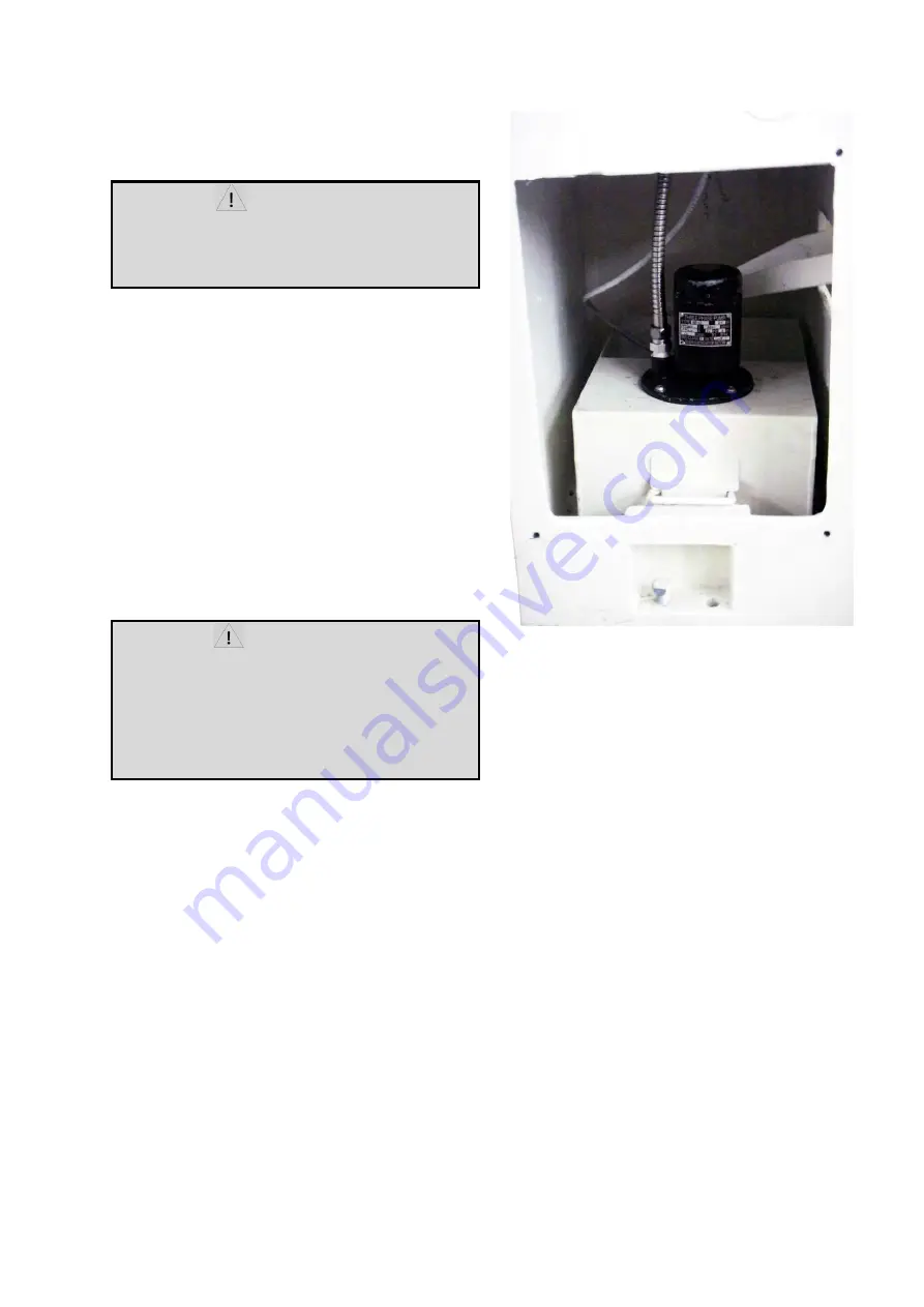
Coolant Preparation
CAUTION
Follow coolant manufacturer’s recommendations
for use, care, and disposal.
1.
Remove rear access cover on tailstock end. Make
sure coolant tank has not shifted during transport and is
located properly under the recovery chute (Fig.9).
2.
Pour three gallons of coolant mix into drip pan.
3.
After machine has been connected to power, turn
on coolant pump and check to see coolant is cycling
properly.
4.
Fasten coolant door to stand.
Electrical connections
WARNING
All electrical connections must be completed by a
qualified electrician!
Failure to comply may cause serious injury and/or
damage to the machinery and property!
The Gear Head Lathe is rated at HP, Ph, V .
Confirm power available at the lathe’s location is the
same rating as the lathe.
Lathe Power Source Junction Box:
Remove the cover, run the main power through the
strain relief bushing and attach the ground, followed by
power lends. Replace the cover.
Main Power Switch:
Located on the backside of the
machine. Turns the power to control machine on and
off.
Make sure the lathe is properly grounded.
Power is connected properly when pulling up on the
forward-reverse lever causes the spindle to rotate
counter-clockwise as viewed from the tailstock. If the
chunk rotates in the clockwise direction, disconnect the
lathe from the power source, switch two of three power
leads, and connect the lathe to the power source.
Fig.9
Summary of Contents for 1440GWI
Page 1: ...OPERATION MANUAL PRECISION GEAR HEAD LATHE MODEL 1440GWI...
Page 18: ...18 Metric Lead and Feed Table Metric Only Inch Thread Table Metric Only...
Page 24: ...1 PARTS LIST ENGINE LATHE...
Page 25: ...2...
Page 29: ...6 Headstock Assembly II...
Page 32: ...9 Headstock Assembly III...
Page 35: ...12...
Page 36: ...13...
Page 37: ...14...
Page 38: ...15...
Page 39: ...16...
Page 40: ...17...
Page 41: ...18...
Page 43: ...20 Apron Assembly II...
Page 45: ...22 Carriage and Cross Slide Assembly...
Page 48: ...25...
Page 50: ...27...
Page 52: ...29 Bed Assembly...
Page 56: ...33 Stand and Brake Assembly...
Page 59: ...36 End Gear Assembly Metric Only...
Page 61: ...38 End Gear Assembly Imperial Only...
Page 66: ...43 Steady Rest...
Page 68: ...45 Coolant And Work Light Assembly...
Page 70: ...47...
Page 71: ...48...
Page 73: ...50 Electrical Schematic Symbol Glossary 1 Phase...
Page 74: ...51 Electrical Schematic Symbol Glossary 3 Phase...


