16
Operation
Feed and Thread selection
1.
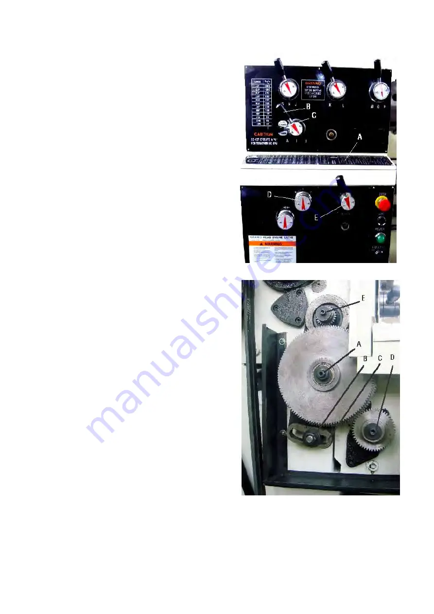
Reference the feed and tread found on the
gearbox faceplate tables (A, Fig.17 & Page 22
of manual).
2.
Move levers (B, C, D, E & F, Fig,.17) to the
appropriate according to the chart.
Change Gears Replacement
The 25T, 127T, 50T gears installed in the end gear
compartment when delivered from the factory. This
combination will cover most inch feeds and threads
under normal circumstance.
The 30Tt, 32T, and two 40T gears found in the
toolbox are used with different combinations as
indicated on feed and thread tables (A, Fig.17).
1.
Disconnect the machine from the power
source (unplug).
2.
Open the door on the left end of the headstock.
3.
Loosen nuts (A & B, Fig.18).
4.
Move quadrant (C, Fig.18) out of the way and
hold in place temporarily by tightening nut (A
& B, Fig.18).
5.
Remove hex socket cap screws (D and/or E,
Fig.18), depending on which gear is to be
changed.
6.
Install new gear(s) and tighten in place with a
hex socket cap screw.
7.
Loosen nut (B, Fig.18), move quadrant back so
teeth mesh on gears, and tighten nuts (A & B,
Fig.18).
Caution
:
Make sure there is a backlash of
0.05mm-0.08mm(0.002
〞
-0.003
〞
)between
gears. Setting the gears too tight will cause
excessive noise and wear.
8.
Close the door and connect the machine to the
power source.
Fig.17
Fig.18
Summary of Contents for 1440GWI
Page 1: ...OPERATION MANUAL PRECISION GEAR HEAD LATHE MODEL 1440GWI...
Page 18: ...18 Metric Lead and Feed Table Metric Only Inch Thread Table Metric Only...
Page 24: ...1 PARTS LIST ENGINE LATHE...
Page 25: ...2...
Page 29: ...6 Headstock Assembly II...
Page 32: ...9 Headstock Assembly III...
Page 35: ...12...
Page 36: ...13...
Page 37: ...14...
Page 38: ...15...
Page 39: ...16...
Page 40: ...17...
Page 41: ...18...
Page 43: ...20 Apron Assembly II...
Page 45: ...22 Carriage and Cross Slide Assembly...
Page 48: ...25...
Page 50: ...27...
Page 52: ...29 Bed Assembly...
Page 56: ...33 Stand and Brake Assembly...
Page 59: ...36 End Gear Assembly Metric Only...
Page 61: ...38 End Gear Assembly Imperial Only...
Page 66: ...43 Steady Rest...
Page 68: ...45 Coolant And Work Light Assembly...
Page 70: ...47...
Page 71: ...48...
Page 73: ...50 Electrical Schematic Symbol Glossary 1 Phase...
Page 74: ...51 Electrical Schematic Symbol Glossary 3 Phase...


