background image

第 7 页

5.

Operation Guide

5.1.

Intelligent circuit breaker

button panel and indicators

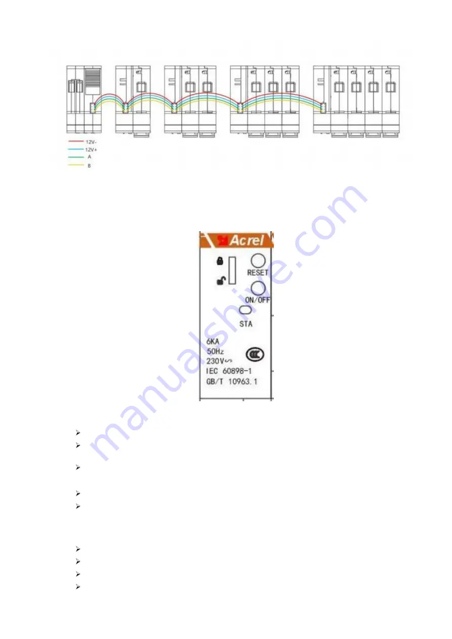
Terminal wiring diagram

Panel

button instruction:

ON/OFF:Short press:On/off brake,Long press 3S:State of repair;

T/ Press once a month or RESET: short press the leakage test button, long

press 3S: alarm RESET and reclosing times return to zero;

Lock:Local lock on and off;

Indicator description:

Green: if 2s off, 0.1s flashing, normal operating status;

Green: If it blinks at an interval of 0.5 seconds, it indicates that the

circuit breaker is in maintenance state (local and remote closing cannot be

performed) ;

Red: If it is steady on, the circuit breaker is closed;

Red: If 2s off, 0.1s flashing, circuit breaker fault;

Red: if the blink interval is 0.5s, the circuit breaker alarms;

Enter automatic address assignment, the traffic light blinks for 0.5s, the

address assignment is finished, and the address is displayed according to the
actual status ;

Summary of Contents for ASCB1 Series

Page 1: ...ASCB1系列智能微型断路器 ASCB1 series intelligent smart circuit breakers 安装使用说明书 V1 0 installation and operation manual 江苏安科瑞电器制造有限公司 Jiangsu Acrel Electric MFG Co Ltd ...

Page 2: ...留一切法律权利 All rights reserved Without written permission of the company any paragraph or chapter in this manual shall not be copied copied reproduced or disseminated in any form Otherwise all consequences shall be borne by the violators The company reserves all legal rights ...

Page 3: ...ndicator description 8 5 3 界面操作 Interface 8 5 3 1 当前设备状态显示 The current device status is displayed 8 1 Summarize ASCB1 series of intelligent miniature circuit breakers are used for low voltage terminal distribution network in industrial commercial civil buildings and infrastructure fields in indoor buildings and similar places The intelligent circuit breaker is used with the intelligent gateway to ...

Page 4: ...ur wire neutral point direct grounding TT low voltage power grid system 2 Product Model Smart circuit breaker Type Function ASCB1 63 Real time monitoring of voltage current power electric energy and temperature parameters standard rS 485 MODBUS communication ASCB1LE 63 Real time monitoring of voltage current power electric energy temperature and leakage parameters standard rS 485 MODBUS communicat...

Page 5: ...lligent circuit breakers can be connected View the real time data of voltage current power electric energy temperature and leakage of each intelligent circuit breaker 3 Technical parameters ASCB1 63 ASCB1LE 63 1P 2P 3P 4P 2P 4P 63A 230V 1P 2P 400V 3P 4P 6A 10A 16A 20A 25A 32A 40A 50A 63A C D 6000A 100 Rated Current warning 110 trip 5 10A Rated current 0 04S 100 Rated power warning 110 trip 100 Rat...

Page 6: ...n self test 20000 times 6000 times IP20 1 35 mm 2000m 10 45 20 70 35mm Din rail installation Smart Gateway technical parameters ASCB1 M 4G ASCB1 M CE AC 220V 30W 4G Ethernet LCD 20 Modbus MQTT 2000m 10 45 20 70 IP20 35mm Din rail installation ...

Page 7: ...第 4 页 4 Installation and wiring 4 1 Appearance and installation size unit mm Smart Circuit Breaker 图1 SCB outline dimensional drawing 图2 Terminal diagram ...

Page 8: ...m 4 2 Installation method 1 The equipment is suitable for standard 35mm guide rail installation installation only need to put the equipment into the track and buckle fixed 2 According to the actual distribution management and line laying design requirements select and use the required ...

Page 9: ...n the handle moves upward the contact moves in the closed direction 4 The nominal cross sectional area of copper wire matching the rated current of circuit breaker is shown in Table 5 Table 5 Rated Current A 10 16 20 25 32 40 50 63 Cable mm 1 5 2 5 4 6 10 16 Torque N m 3 5 3 5 3 5 3 5 3 5 3 5 5 During installation please tighten the copper wire with the torque specified in Table 5 After installati...

Page 10: ...第 6 页 Maximun number 18 ...

Page 11: ...cator description Green if 2s off 0 1s flashing normal operating status Green If it blinks at an interval of 0 5 seconds it indicates that the circuit breaker is in maintenance state local and remote closing cannot be performed Red If it is steady on the circuit breaker is closed Red If 2s off 0 1s flashing circuit breaker fault Red if the blink interval is 0 5s the circuit breaker alarms Enter au...

Page 12: ...shing circuit breaker fault Red If the blink interval is 0 5s there is a circuit breaker alarm 5 3 Interface 5 3 1 The current device status is displayed You can query the device status of each device by pressing and The device status page is displayed as follows Note The status definition table is as follows Symbol Definition Warning None Have early warning None Have malfunction None Have Recondi...

Page 13: ...Lock Can remote Locked can t remote 第 8 页 ...

Reviews: