Series 461A User's Manual Single/Dual Alarm
___________________________________________________________________________________________
- 2 -
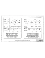
The alarm setpoints are individually adjustable over the full input
range of the unit and the deadband for each setpoint is adjustable
from 1 to 100 percent. The setpoint voltage for each channel may
be monitored via DVM testpoints accessible from the front of the
unit. The deadband adjustment does not affect setpoint adjustment.
Rather, it determines the amount the input signal has to return into
the normal operating range before the relay contacts will transfer.
Deadband is normally used to eliminate false trips or alarm "chatter"
caused by fluctuations in the process input near the alarm point.
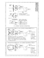
To implement an AC Current alarm for inputs up to 20A, an
optional AC current sensor (Acromag Model 5020-350, ordered
separately) is used in conjunction with the 0 to 1V DC (-V1) input
type configured for current input (external jumper required). The full-
scale output of this transducer is 11.17mA DC. An internal 50
Ω
shunt resistor installed in the module converts the 0-11.17mA
transducer signal to a 0-0.5585V DC input signal. The sensor itself
is an insulated, highly accurate toroidal instrument transformer, that
outputs a safe, low-level DC milliamp signal to the 461A’s analog
input terminals. The sensor is intended to be mounted close to the
current being measured and the wire connecting the sensor to the
461A’s input terminals can be up to 400 feet long (18 gauge wire).
The AC current input span is simply determined by the number of
primary turns passing through the center of the toroid. Example: a 0
to 20A AC input range requires one turn to pass through the hole in
the sensor, while a 0 to 5A AC input range requires four turns. See
specifications for other ranges.
The 461A alarm is RFI-protected, operates over a wide
temperature range, and features excellent temperature coefficients
which minimize the effects from harsh plant environments. It is
available for 115V AC, or 230V AC power (for DC power, see the
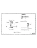
Acromag Series 361A alarms). The versatile DIN rail mount can
accomodate a variety of mounting applications. See Drawing
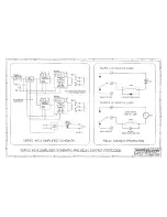
4501-544 for a simplified schematic.
Alarm input and power wiring is inserted at the top of the unit,
while output contact wiring is inserted at the bottom of the unit.
Screws to secure the wiring are located on the front panel.
Connectors are screw-clamp type and accept wire size from 26 to
14 AWG.
Key 461A Features:
•
Process Current or Voltage Input
•
Green/Red LED Trip/Power Indicators
•
Single or Dual Alarm
•
15-turn Setpoint Adjustment
•
HIGH/LOW Alarm Operation
•
15-turn Deadband Adjustment
•
Failsafe/Non-Failsafe Mode
•
Wide Ambient Temperature Range (-25
°
C to +75
°
C)
•
Mechanical Relay - 5A Contacts
•
AC Powered: 115V AC or 230V AC
•
Automatic Alarm Reset
•
No Point-to-Point Internal Wiring
•
Easy Field Jumper Configuration
•
Setpoint Voltage Monitor Points
SPECIFICATIONS:
Function: This family of single or dual, DIN-rail mounted, AC-
powered alarms, accept either a process current or voltage input
signal and provide a single or dual mechanical relay output.
Internal jumpers allow the alarm to be field-configured for use as
a HIGH or LOW alarm, in either Failsafe or Non-Failsafe
operating modes. The unit provides three-way isolation between
input, output, and power. Setpoint and Deadband adjustments
utilize 15-turn potentiometers. The Setpoint voltage can be
monitored via testpoints at the front panel (0-5V represents 0-
100% of input voltage span). The Deadband adjustment is a
'blind' adjustment between 1% and 100% of span. Red and
green status LED's provide a visual indication of the alarm
condition for each channel.
MODEL/SERIES: 461A- (Color coded with a Yellow label)
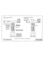
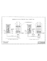
INPUT: Unit can also be configured at the input terminal block for
either current or voltage input (-V1 and -V5 models only), see
connection diagram 4501-542. All input circuits utilize a high
impedance pull-down resistor (1M
Ω
for -V1 and -V5 units).
-V1:
0 to 1V DC with 1M
Ω
minimum input impedance or 4 to
20mA DC into 50
Ω
shunt resistor (jumper required).
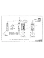
This range used with optional AC Current Sensor 5020-
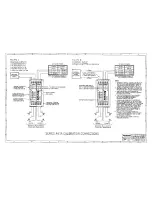
350 (see drawings 4501-542 and 4501-546 for details).
-V5:
0 to 5V DC with 1M
Ω
minimum input impedance or 4 to
20mA DC into 250
Ω
shunt resistor (jumper required).
-V0:
0 to 10V DC with 100K
Ω
minimum input impedance.
-V50:
0 to 50V DC with 500K
Ω
minimum input impedance.
-V100: 0 to 100V DC with 1M
Ω
minimum input impedance.
IMPORTANT: For the -V1 and -V5 input ranges, the 4-20mA
DC input range is selected via the installation of an external
jumper between the Input (L) and Input (+) terminals. This
connects an internal shunt resistor to the input.
AC Current Sensor (5020-350): Optional - This sensor is a highly
accurate toroidal instrument transformer used to convert an AC
current signal to a low level DC milliampere signal of 0 to
11.17mA. The input AC current range is a simple function of
the number of turns placed on the AC Current Sensor (see
Table 2 below). The user configures the AC current sensor with
the required number of primary turns to obtain the desired input
span.
Table 2: AC Sensor Turns
AC CURRENT
INPUT RANGE
PRIMARY
TURNS
SENSOR OUTPUT
(RED/BLACK WIRES)
0 to 20 Amps AC
1
0 to 11.17mA DC
0 to 10 Amps AC
2
0 to 11.17mA Dc
0 to 5 Amps AC
4
0 to 11.17mA DC
0 to 2 Amps AC
10
0 to 11.17mA DC
0 to 1 Amps AC
20
0 to 11.17mA DC
The output wires of the sensor are polarized: Red is (+) plus and
Black is (-) minus. Normally, these wires are attached to one
end of a cable (user supplied) and the other end connects to
one of the analog input's (+) and (-) terminals.
Input Burden: A function of the wire gauge resistance used for
the primary turns.


