


Series 461A User's Manual Single/Dual Alarm
___________________________________________________________________________________________
- 4 -
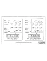
Response Time: A built-in fixed time delay of 100 milliseconds
typical. That is, the relay will transfer
≤
100 milliseconds after
the input signal exceeds the setpoint. This delay helps prevent
false alarming due to transient interference. The relay will
transfer within 50mS after the input passes the deadband
region, as it returns into the normal range. The Red LED will
light as soon as the input signal exceeds the setpoint, but the
relay will not transfer until after the time delay has expired.
When calibrating the alarm, the LED's should be observed to
indicate proper setpoint position.
Noise Rejection - Common Mode: Better than 100dB at 60 Hz,
250
Ω
unbalance, typical. Normal Mode: 26dB at 60 Hz, 250
Ω
source, typical.
RFI Resistance: The unit will not trip under the influence of RFI
when the input is
±
0.5% of input span from the setpoint voltage
for RFI field strengths up to 10V/meter, at frequencies of
27MHz, 151MHz, and 467MHz.
EMI Resistance: Unit will not trip when input is
±
0.25% of input
span from the setpoint voltage with switching solenoids or
commutator motors.
Surge Withstand Capability (SWC): Input/Output terminations
are rated per ANSI/IEEE C37.90-1978. Unit is tested to a
standardized test waveform that is representative of surges
(high frequency transient electrical interference) observed in
actual installations.
Construction (Basic Alarm):
Printed Circuit Boards: Military grade FR-4 epoxy glass circuit
board, 0.063 inches thick.
Printed Circuit Board Coating: Fungus resistant acrylic
conformal coat.
Terminals: Compression type, wire size 14 AWG maximum.
Case: Self-extinguishing black NYLON Type 6.6 polyamide
thermoplastic, UL94 V-2. General Purpose, NEMA Type 1
enclosure.
Jumpers: Gold flash over nickel contacts.
Testpoints (Setpoint Voltage): Will accept up to an 0.080”
diameter probe tip. Do not insert probe tip more than 0.4” deep.
Mounting Position: Position insensitive.
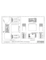
MOUNTING:
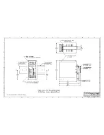
-DIN: General Purpose Housing, DIN-Rail Mount - accepts both
"G" Rail (32mm), Type EN50035, or "T" Rail (35mm), Type
EN50022. Refer to Drawing 4501-252 for outline and
clearance dimensions. Shipping Weight: 1 pound (0.45 Kg)
packed.
CERTIFICATION: Consult the factory for current information on the
availability of agency (e.g. Canadian Standards Association,
Factory Mutual, etc.) approvals.
-NCR: No Certification Required.
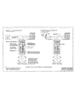
INSTALLATION:
The alarm is packaged in a general purpose type of enclosure.
Use an auxiliary enclosure to protect against unfavorable
environments and locations. Maximum operating ambient
temperatures should be within -13 to 167oF (-25 to 75oC) for
satisfactory performance. Connect as shown in the Connection
Diagram 4501-542. To verify calibration, refer to the
"CALIBRATION" section.
Mounting: Mount alarm assembly - refer to Drawing 4501-540 for
mounting and clearance dimensions.
DIN Rail Mounting: Use suitable fastening hardware to secure
the DIN rail to the designated mounting surface. The alarm is
supplied with the DIN Rail mounting option (-DIN) and can be
mounted to either a "T" or "G" style rail. Installation of the alarm
to the rail depends on the type of DIN rail used. Units can be
mounted side by side on 1.6 inch centers, if required.
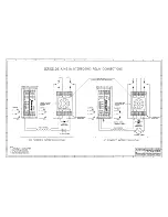
"T" Rail (35mm), Type EN50022: To attach an alarm to this
style of DIN rail, angle the top of the unit towards the rail and
locate the top groove of the adapter over the upper lip of the rail.
Firmly push the unit towards the rail until it snaps solidly into
place. To remove an alarm, insert a screwdriver into the lower
arm of the connector and pull downwards while applying
outward pressure to the bottom of the unit.
"G" Rail (32mm), Type EN50035: To attach an alarm to this
style of DIN rail, angle the unit so that the upper groove of the
adapter hooks under the top lip of the rail. Firmly push the unit
towards the rail until it snaps solidly into place. To remove an
alarm, pull the lower part of the unit outwards until it releases
from the rail and lift the unit from rail.
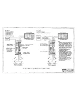
Electrical Connections:
The wire size used to connect the unit to the control system is
not critical. All terminal strips can accommodate wire from 14-26
AWG. Strip back wire insulation 1/4-inch on each lead before
installing into the terminal block. Input wiring may be shielded or
unshielded twisted pair. Since common mode voltages can exist on
signal wiring, adequate wire insulation should be used and proper
wiring practices followed. It is recommended that input wiring be
separated from relay contact wiring for safety, as well as for low
noise pickup.
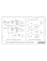
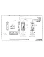
1. Power (Refer to Drawing 4501-542 for power connections):
The label on the unit specifies the AC power requirements.
Connect AC power as shown in Drawing 4501-542. Use
suitable wire per applicable codes. For 115VAC units, connect
the AC HOT power lead to the (L1) terminal and the AC
NEUTRAL power lead to the terminal marked (W). For 230VAC
units, connect the AC L1 power lead to the (L1) terminal and AC
L2 power lead to the terminal marked (L2). Connect the AC
GROUND lead to the (G) terminal (the AC Ground (G) terminal
is not connected internally).
2. Grounding: The alarm housing is plastic and does not require
an earth ground connection. If the alarm is mounted in a metal
housing, a ground wire connection is required. Connect the
ground terminal of the metal housing (Green Screw) to a
suitable earth ground using appropriate wire per applicable
codes.


