AVME941X/946X DIGITAL I/O BOARDS
_________________________________________________________________________________
- 12
-
2.8 USE WITH SOLID STATE RELAYS
The AVME 94XX Digital I/O Board may interface with industry standard solid state relays and termination panels
PB16A, PB32 and their equivalents.
2.8.1 Configuring The AVME - 94XX
On the AVME94XX, the following jumpers or shorting clips should be in place: J2, J4, J6 and J10. Pullup resistor
networks R1, R2, R3, R4, R5, R6, R7 and R8 are removable.
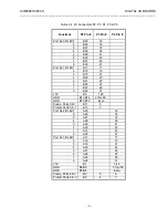
Table 2.6 lists the Module Number Bit Positioning for the I/O port registers.
TABLE 2.6 Module Number Bit Positioning
I/O Port
Number
Module Number
7 6 5 4 3 2 1 0
PB16A connected
to
N+0
7 6 5 4 3 2 1 0
P3
N+1
15 14 13 12 11 10 9 8
P3
N+2
7 6 5 4 3 2 1 0
P4
N+3
15 14 13 12 11 10 9 8
P4
N+4
7 6 5 4 3 2 1 0
P5
N+5
15 14 13 12 11 10 9 8
P5
N+6
7 6 5 4 3 2 1 0
P6
N+7
15 14 13 12 11 10 9 8
P6
For bit positions corresponding to output modules, a 1 state will turn the I/O point on and the output latch will sink
current. A 0 state will turn the module off. For bit positions corresponding to input modules, a 1 state indicates the
presence of a low voltage for the "on" state of the module.
A 0 state indicates a high voltage present.
2.8.2 Configuring The PB16A
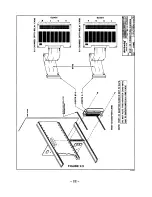
If the PB16A is to get power from the AVME94XX, install a jumper at pin 1 or pin 49 on the PB16A termination
panel. Install appropriate solid state relay modules. Connect the 50 Pin ribbon cable between PB16A and the
AVME94XX observing the pin 1 index mark.
2.9 USE WITH OTHER DEVICES
The AVME946X/941X Digital Boards can interface with a variety of discrete devices such as relays, switches,
contact closures, and indicators. Optional termination panel 6980-16U can be used to connect field wiring to the
digital I/O card. The following guidelines should be followed to insure proper interfacing.
2.9.1 Relays And Other Inductive Loads
When driving relays coils or other inductive loads, the PROTECT line should be tied to the voltage supply of the
loads. This puts a diode accross each load to limit the voltage spike generated when an inductive load is switched
off quickly. Since PROTECT is common to all 16 outputs, the supply voltage for all of the loads must be the same.
Otherwise, each load will have to have its own external diode. The pullup resistors should be removed from the
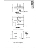
digital I/O card also. See figure 2.7 Relay Driver and Input Configurations, for relay driver configurations.


