AVME941X/946X DIGITAL I/O BOARDS
_________________________________________________________________________________
- 6
-
Adequate air circulation must be provided to prevent a temperature rise above the maximum operating
temperature. Large and continuing fluctuations in ambient air temperature should be avoided. If the installation is
in an industrial environment and the board is exposed to environmental air, careful consideration should be given
to air filtering.
2.3 BOARD CONFIGURATION
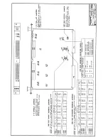
The Digital I/O Board may be configured in a variety of ways for many different applications. Each possible jumper
setting will be discussed in the following sections. The jumper locations are shown in Figure 2.1.
2.3.1 Default Jumper Configuration
VMEBUS INTERFACE CONFIGURATION
When a board is shipped from the factory, it is configured as follows:
•
VMEbus Short I/O Address of 0000H.
•
Set to respond to both Address Modifiers 2DH.
2.4 ADDRESS ASSIGNMENT
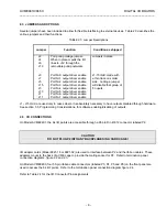
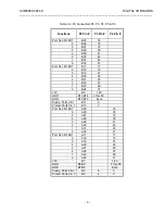
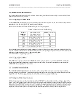
Jumpers J17, J18, and J19 are used to establish the base address for the 1k byte block of memory the AVME
94XX will occupy in the Memory Map. J17 and J18 selects the base address. An open, or no jumper installed,
corresponds to a logic 0 state. Refer to Table 2.2 Address Decoding. J19 selects the address modifier codes and
the Standard or Short Memory Map. An open on J19 pins 1 and 2 selects only the Supervisory Access (3DH or
2DH) code. A short on J19 pins 1 and 2 will allow the card to recognize both the Supervisory and the Non-
Priviledged Access codes. An open, or no jumper installed, on J19 pins 3 and 4 selects Short Memory Map. A
short, or jumper installed, selects Standard Memory Map. Refer to Table 2.1.
Table 2.1 VMEbus Address Modifier Codes
Jumper J19
Address Modifier
Addressing Mode
Pins
3 & 4
Pins
1 & 2
Codes Recognized
OUT
OUT
2DH
Short Supervisory
OUT
IN
2DH OR 29H
Short Supervisory or
Short Non-Priveledged
IN
OUT
3DH
Standard Supervisory
IN
IN
3DH OR 39H
Standard Supervisory or
Standard Non-Priveledged


