BusWorks® 961/962EN User’s Manual Modbus TCP/IP Differential I/V Input
__________________________________________________________________
_______________________________________________________________________________________
Acromag, Inc. Tel:248-624-1541 Fax:248-624-9234 Email:
sales@acromag.com
http://www.acromag.com
20
7
4
1
6
8
5
2
3
+3.3V
IN5+
IN3+
IN3-
IN4-
IN2-
IN0-
IN1+
IN0+
-6V
MUX
+6V
+
AIN1
-
STA
-6V
ACT
+6V
LINK
+3.3V
+3.3V
ISOLATED
FLYBACK
SWITCHER
GND
IN4+
IN5-
IN1-
IN2+
M
U
X
M
U
X
+
AIN2
-
5V
RJ45
P
O
W
E
R
I/O POWER
DC+
+6V
+1.6V
BIAS
-6V
+6V
I/O LOGIC
POWER
TOGGLE SWITCH
MICRO
CONTROLLER
MICRO
CONTROLLER
RUN
+3.3V
+3.3V
+3.3V
+5V
+5V
3.3V
EARTH GROUND
Ethernet Port Includes
ESD Protection
-6V
DC-
15-36VDC
FLASH
(512Kx8)
SRAM
(512Kx8)
ETHERNET
CONTROLLER
A/D
CONVERTER
NEG VOLTAGE
CONVERTER
ISOLATED INPUT POWER
ISOLATED ETHERNET
INPUTS 0, 1, & 2 MUST
BE SAME TYPE
INPUTS 3, 4, & 5 MUST
BE SAME TYPE
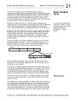
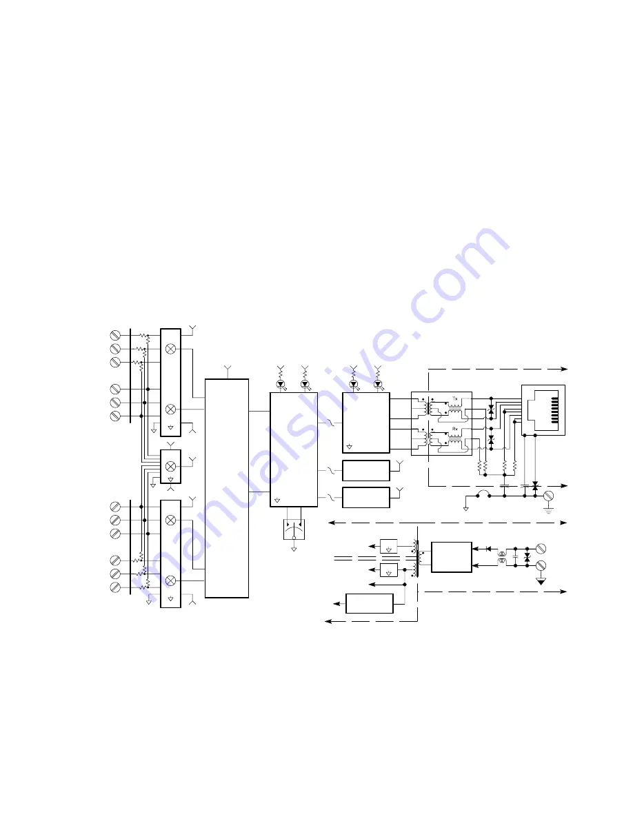
These input modules provide up to six process current (961EN), or six
differential DC voltage (962EN) input channels, and provide an isolated
10/100 Ethernet interface for configuration, monitoring, and control of the
input module. The current input model (961EN) uses precision 24.9
Ω
current sink resistors across the inputs. Voltage input models use 10:1
precision resistor voltage dividers at the input. A multiplexer is used to
connect each input voltage to an A/D converter (separate A/D channels
serve 3 input channels each). The A/D converter then applies appropriate
gain to the signals, performs analog-to-digital conversion, and digitally filters
the signals. The microcontroller completes the transfer function according to
the input type and its embedded program. Configuration and calibration
parameters are stored in non-volatile memory integrated within the
microcontroller. A dedicated Ethernet controller handles Ethernet
communication. The I/O terminals and the Ethernet port terminals also
include transient suppression. A wide input switching regulator (isolated
flyback) provides isolated power to the I/O circuits and the Ethernet
controller. Refer to the simplified schematic shown below to help gain a
better understanding of the circuit.
Note that input types may vary between the two channel groups—channel 0,
1, and 2 may be configured differently from channel 3, 4, and 5. Inputs are
not isolated channel-to-channel, except for small common mode voltage
differences in the range of ±5V (961EN), or ±12V (962EN).
HOW IT WORKS


