ACEX4041 COM Express Type 10
AcroPack Carrier Board
- 44 -
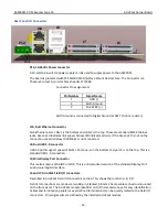
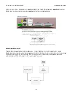
JTAG
A JTAG interface is provided for programming and debugging FPGAs on
AcroPack modules. It is intended to be used with a Xilinx Platform USB II
programming device. A bypass circuit is included that will detect a vacant
AcroPack site and close a switch to complete the JTAG chain. When four
AcroPack modules with Xilinx FPGAs are installed on the carrier the module in
slot D appears first in the chain followed by the module in slot C, B, and A. The
slot address CPLD is also included in the JTAG chain for factory programming.
Ethernet Controllers
Two ethernet controllers are used to provide two independent ethernet
ports. The Intel i210 was chosen for the ACEX4041. The i210 is a low power
component that supports Gb ethernet. Uses the PCIe Gen 2 interface to the
PCIe switch to communicate through to the host CPU.
M.2
This M.2 interface is intended for SSD devices only. This is a SATA based
expansion site. Supports SATA III devices, speeds up to 6Gb/s. Can except
modules that are SSD Socket 2 (mechanical Key B) and for modules that are
SSD Socket 3 (mechanical key M). This site supports sizes 2242, 2260 and
2280. For more information about M.2 see the PCI-SIG, PCI Express M.2
Specification 1.0 or later The M.2 uses the SATA signals directly from the host
CPU.
5.
SERVICE AND REPAIR
Surface-Mounted Technology (SMT) boards are generally difficult to repair. It
is highly recommended that a non-functioning board be returned to Acromag
for repair. The board can be damaged unless special SMT repair and service
tools are used. Further, Acromag has automated test equipment that
thoroughly checks the performance of each board. .
Please refer to Acromag's Service Policy Bulletin or contact Acromag for
complete details on how to obtain parts and repair.
PRELIMINARY SERVICE PROCEDURE
CAUTION: POWER MUST BE TURNED OFF BEFORE REMOVING OR INSERTING BOARDS
Before beginning repair, be sure that all of the procedures in Section 2,
PREPARATION FOR USE, have been followed. Also, refer to the
documentation of your carrier board to verify that it is correctly configured.
Verify that there are no blown fuses. Replacement of the carrier and/or
AcroPack with one that is known to work correctly is a good technique to
isolate a faulty board.

