SERIES AP440 ACROPACK
USER
’S MANUAL
Acromag, Inc. Tel: 248-295-0310
- 10 - http://www.acromag.com
- 10 -
www.acromag.com
2.2 Installation Considerations
IMPORTANT: Adequate air
circulation must be provided to
prevent a temperature rise
above the maximum operating
temperature.
Refer to the specifications section for loading and power requirements. Be
sure that the system power supplies are able to accommodate the power
requirements of the system boards, plus the installed Acromag board,
within the voltage tolerances specified.
In an air cooled assembly, adequate air circulation must be provided to
prevent a temperature rise above the maximum operating temperature and
to prolong the life of the electronics. If the installation is in an industrial
environment and the board is exposed to environmental air, careful
consideration should be given to air-filtering.
In a conduction cooled assembly, adequate thermal conduction must be
provided to prevent a temperature rise above the maximum operating
temperature.
2.3 Board Configuration
Power should be removed from the board when installing AP modules,
cables, termination panels, and field wiring. Model AP440 digital input
boards have no hardware jumpers or switches to configure.
2.4 Field I/O Connector
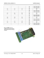
A field I/O interface connector provides a mating interface between the AP
modules and the carrier board. The 100 pin ST5-50-1.50-L-D-P-TR Samtec
connector is used on the AcroPack card as board to board interconnect.
This connector will mate with the 100 pin SS5-50-3.00-L-D-K-TR Samtec
connector on the carrier. The stack height is 4.5mm.
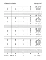
Pin assignments are unique to each AP model. Table 2.1 lists signal pin
assignments for the module field I/O connector. Every other pin of the 100
pin connector is left unconnected in order to meet the minimum creepage
distance required for 60 Volt isolation.

