background image

SERIES AP440 ACROPACK  

USER

’S MANUAL 


Acromag, Inc. Tel: 248-295-0310  

          - 12 -                                   http://www.acromag.com  

- 12 - 

www.acromag.com 


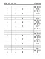
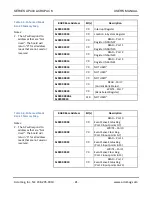
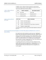
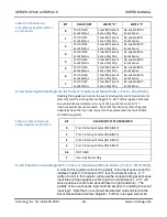
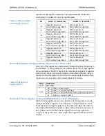
40 

Reserved/isolation 


39 

Reserved/isolation 

11 

11 

21 

42 

Field I/O 17 

45 

36 

22 

41 

Field I/O 18 


44 

Reserved/isolation 


43 

Reserved/isolation 

12 

12 

23 

46 

Field I/O 19 

46 

37 

24 

45 

Field I/O 20 


48 

Reserved/isolation 


47 

Reserved/isolation 

13 

13 

25 

50 

NC 

47 

38 

26 

49 

Field I/O 21 


52 

Reserved/isolation 


51 

Reserved/isolation 

14 

14 

27 

54 

Field I/O 22 

48 

39 

28 

53 

Field I/O 23 


56 

Reserved/isolation 


55 

Reserved/isolation 

15 

15 

29 

58 

Field I/O 24 

49 

40 

30 

57 

CCOM 


60 

Reserved/isolation 


59 

Reserved/isolation 

16 

16 

31 

62 

Field I/O 25 

50 

41 

32 

61 

Field I/O 26 


64 

Reserved/isolation 


63 

Reserved/isolation 

17 

17 

33 

66 

Field I/O 27 

51 

42 

34 

65 

Field I/O 28 


68 

Reserved/isolation 


67 

Reserved/isolation 

18 

18 

35 

70 

NC 

52 

43 

36 

69 

Field I/O 29 


72 

Reserved/isolation 


71 

Reserved/isolation 

19 

19 

37 

74 

Field I/O 30 

53 

44 

38 

73 

Field I/O 31 


76 

Reserved/isolation 


75 

Reserved/isolation 

20 

20 

39 

78 

Field I/O 32 

54 

45 

40 

77 

DCOM 


80 

Reserved/isolation 


79 

Reserved/isolation 

21 

21 

41 

82 

NC 

55 

46 

42 

81 

NC 

Summary of Contents for Acropack AP440 Series

Page 1: ...Module With Interrupts USER S MANUAL ACROMAG INCORPORATED 30765 South Wixom Road Wixom MI 48393 2417 U S A Tel 248 295 0310 Fax 248 624 9234 Copyright 2016 Acromag Inc Printed in the USA Data and spec...

Page 2: ...3 1 Ordering Information 5 1 3 2 Key Features 5 1 3 3 Key Features PCIe Interface 6 1 4 Signal Interface Products 7 1 5 Software Support 7 Windows 7 VxWorks 7 Linux 7 1 6 References 8 2 0 PREPARATION...

Page 3: ...26 Event Interrupt Status Register for Ports 0 3 Enhanced Mode Bank 1 Port 6 Read Only 26 Table 3 13 Event Interrupt Status Register for Ports 0 3 26 Event Polarity Control Register For Ports 0 3 Enha...

Page 4: ...ervice and Repair Assistance 38 5 2 Preliminary Service Procedure 38 5 3 Where to Get Help 38 6 0 SPECIFICATIONS 40 6 1 Physical 40 6 2 Power Requirements 40 6 3 Environmental Considerations 40 6 3 1...

Page 5: ...ticular purpose Further Acromag assumes no responsibility for any errors that may appear in this manual and makes no commitment to update or keep current the information contained in this manual No pa...

Page 6: ...olarity debounce and interrupt support Inputs also include hysteresis for increased noise immunity The AP440 utilizes state of the art Surface Mounted Technology SMT to achieve its wide functionality...

Page 7: ...ust pass before the input transition is recognized as valid at the FPGA input This helps prevent false events and increases noise immunity Reverse Polarity Protection Bipolar inputs are not polarized...

Page 8: ...consists of low level drivers and Dynamic Link Libraries DLLs that are compatible with a number of programming environments The DLL functions provide a high level interface to boards eliminating the n...

Page 9: ...www acromag com 8 www acromag com 1 6 References The following resources regarding AcroPack modules are available for download on Acromag s website or by contacting your sales representative PCI Expre...

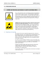
Page 10: ...etic or radioactive fields unless the device is contained within its original manufacturer s packaging Be aware that failure to comply with these guidelines will void the Acromag Limited Warranty 2 1...

Page 11: ...should be given to air filtering In a conduction cooled assembly adequate thermal conduction must be provided to prevent a temperature rise above the maximum operating temperature 2 3 Board Configura...

Page 12: ...3 3 5 10 NC 37 28 6 9 Field I O 5 12 Reserved isolation 11 Reserved isolation 4 4 7 14 Field I O 6 38 29 8 13 Field I O 7 16 Reserved isolation 15 Reserved isolation 5 5 9 18 Field I O 8 39 30 10 17...

Page 13: ...O 22 48 39 28 53 Field I O 23 56 Reserved isolation 55 Reserved isolation 15 15 29 58 Field I O 24 49 40 30 57 CCOM 60 Reserved isolation 59 Reserved isolation 16 16 31 62 Field I O 25 50 41 32 61 Fi...

Page 14: ...5 NC 88 Reserved isolation 87 Reserved isolation 23 23 45 90 NC 57 48 46 89 NC 92 Reserved isolation 91 Reserved isolation 24 24 47 94 NC 58 49 48 93 NC 96 Reserved isolation 95 Reserved isolation 25...

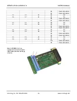
Page 15: ...dule Likewise pin assignments are identical to those of Acromag Model AP408 Note that the inputs of this device are bipolar and may be connected in any polarity with respect to the port common Further...

Page 16: ...ule carriers and conduction cooling kit to provide additional stability for harsh environments Power supplies 5 12 and 12 Volt have been assigned to pins that are reserved in the mini PCIe specificati...

Page 17: ...COEX1 1 4 GND 1 N C WAKE 1 2 3 3V3 Note 1 The following mini PCIe signals are not used by the AP440 USB_D USB_D WAKE LED_WPAN LED_WLAN LED_WWAN W_DISABLE COEX1 COEX2 UIM_C4 UIM_C8 Note 2 5 12 and 12 V...

Page 18: ...card The system software accesses the configuration registers to determine how many blocks of memory space the module requires It then programs the board s configuration registers with the unique memo...

Page 19: ...at the base address for the board BAR0 in memory space must be added to the addresses shown to properly access these AP440 registers Register accesses as 32 16 and 8 bit data in memory space are permi...

Page 20: ...to determine the function required Standard Default Mode Memory Map Table 3 2 shows the memory map for the Standard Mode of operation This is the Default mode reached after power up or system reset S...

Page 21: ...08 IN15 0x0000 0010 7 0 READ1 Port 2 Register IN16 IN23 0x0000 0014 7 0 READ1 Port 3 Register IN24 IN31 0x0000 0018 7 0 NOT USED2 0x0000 001C 7 0 NOT USED2 0x0000 0020 7 0 NOT USED2 0x0000 0024 7 0 RE...

Page 22: ...18 7 0 NOT USED2 0x0000 001C 7 0 NOT USED2 0x0000 0020 7 0 NOT USED2 0x0000 0024 7 0 READ Port 7 Current Bank Status 0x0000 0024 7 0 WRITE Port 7 Bank Select Register 0x0000 0028 0x00000040 31 0 NOT U...

Page 23: ...ent Bank Status Reg 0x0000 0024 7 0 WRITE Port 7 Bank Select Register 0x0000 0024 7 0 WRITE Port 7 Also Bank Select Register 0x0000 0028 0x00000040 31 0 NOT USED2 Table 3 6 Enhanced Mode Bank 2 Memory...

Page 24: ...hen both enabled will allow interrupts to be generated Changing Debounce control registers while interrupts are enabled can cause false interrupts It is recommended that interrupts be disabled prior t...

Page 25: ...rt assigns the least significant data line D0 to the least significant input line of the port grouping e g IN00 for port 0 to D0 A read of this register returns the status ON OFF of the input point Do...

Page 26: ...ent Sense Status Clear Registers For IN00 IN31 Enhanced Mode Bank 1 Ports 0 3 Read Write Each input line of each port includes an event sense input Reading each port will return the status of each inp...

Page 27: ...atus of input ports 0 3 bits 0 3 and the interrupt status flag bit 7 Bit 7 of this register indicates an event sense was detected on any of the 4 event sense ports 1 interrupt asserted event sensed No...

Page 28: ...rough IN31 Bank Select Register Enhanced Mode Bank 1 Port 7 Write Only Bits 6 7 of this register are used to select monitor the bank of registers to be addressed In Enhanced Mode three banks banks 0 2...

Page 29: ...nput ports or event signals to insure valid data Table 3 17 Debounce Control Register Note that any registers bits not mentioned will remain at the default value logic low Bit s FUNCTION 0 Port 0 IN00...

Page 30: ...e Bank 2 Port 3 Write Only This register bit is used to reset the debounce circuitry If bit 0 of this register is 0 default value the debounce circuitry is not reset If bit 0 is set to 1 then the inte...

Page 31: ...r Read Write BAR0 48H This read write register will access the XADC register at the address set in the XADC Address Register allowing the module s key supply voltages and FPGA junction temperature to...

Page 32: ...m Temperature 0x25 Minimum Vccint 0x26 Minimum Vccaux Table 3 21 FPGA Voltage and Temperature Range Symbol Minimum Typical Maximum Vccint 0 95 1 0 1 05 Vccaux 1 71 1 8 1 89 Recommended Operating Tempe...

Page 33: ...t lines a port are isolated and gated to the data bus D0 D7 lines A high input will read as 1 and all inputs include hysteresis and programmable debounce Enhanced Operating Mode In the Enhanced Mode o...

Page 34: ...be detected On the AP440 if change of state detection for an input signal is desired two channels connected to the same input signal would be required one sensing positive transitions one sensing neg...

Page 35: ...ut point while the state refers to its current level An enabled Event Sense bit and the board interrupt enabled when both enabled will allow interrupts to be generated Changing Debounce control regist...

Page 36: ...tting bit 0 of the Debounce Control Register Write 01H to the Port 0 address of this bank Debounce Control Register If the module had been configured earlier you would first read this register to chec...

Page 37: ...errupt Enable bit 0 1 To enable further interrupts to occur for an event that has already occurred for an I O point the Event Sense Status Register must be written with a 1 to reenable event sensing f...

Page 38: ...ingle port share a common connection individual outputs are not isolated from each other within the same port However separate port commons are provided to facilitate port to port isolation Input opto...

Page 39: ...ON POWER MUST BE TURNED OFF BEFORE SERVICING BOARDS Before beginning repair be sure that all of the procedures in the Preparation for Use section have been followed Also refer to the documentation of...

Page 40: ...SERIES AP440 ACROPACK USER S MANUAL Acromag Inc Tel 248 295 0310 39 http www acromag com 39 www acromag com Email solutions acromag com Phone 248 295 0310...

Page 41: ...AC peak 40oC to 85oC1 2 AP440 3E LF 38V to 60V DC or AC peak 40oC to 85oC1 2 Note 1 An air cooled application with an AcroPack module will require a minimum airflow of 200LFM Note 2 Applications requi...

Page 42: ...trength test for one minute without breakdown 6 3 4 Vibration and Shock Standards The AcroPack complies with the following Vibration and Shock standards Vibration Sinusoidal Operating Complies with IE...

Page 43: ...an appropriate pullup to 5V Input Hysteresis 80mV Typical Input Capacitance 45pF Typical Turn On Time Measured to the point of positive event interrupt detection 15us Typical 25 C for a 0 to threshol...

Page 44: ...1 Line Speed Gen1 2 5Gbps Available through system connector Lane Operation 1 Lane 4K Memory Space Required One Base Address Register BAR Input Current Varies according to model number and input signa...

Page 45: ...er is 20 Bytes with data payload of 4 Bytes for our typical AcroPack For each 4 Byte data sample 24 Bytes are sent 10 4 M samples sec or 41 6 M Bytes sec or 0 332 G bit sec Note 3 For our typical Acro...

Page 46: ...Tel 248 295 0310 45 http www acromag com 45 www acromag com Appendix A AP CC 01 Heatsink Kit Installation This example will show how to install the AP CC 01 Heatsink kit with an APCe7020 carrier AP CC...

Page 47: ...ACK USER S MANUAL Acromag Inc Tel 248 295 0310 46 http www acromag com 46 www acromag com 1 Install two standoffs and secure with two screws 2 Install the AcroPack module 3 Install the Heatsink and se...

Page 48: ...S AP440 ACROPACK USER S MANUAL Acromag Inc Tel 248 295 0310 47 http www acromag com 47 www acromag com 4 AP CC 01 Installation is complete Note Make sure the thermal pad is making contact with the FPG...

Page 49: ...ATED INPUT I O INTERFACE SIMPLIFIED INPUT CHANNEL NOTE FOUR PORTS OF EIGHT CHANNELS ARE PROVIDED SEPARATE PORT COMMONS ENSURE PORT TO PORT ISOLATION IO31 INPUT VOLTAGE RANGE AP440 1 4 18V DC OR AC PEA...

Page 50: ...N AP440 PORT AND THE COMMON LINE OF AN AP445 PORT DO NOT NECESSARILY CONNECT TOGETHER THE AP440 AP445 INCLUDE 4 PORTS OF 8 CHANNELS EACH EACH PORT SHARES A PORT COMMON SEPARATE PORT COMMONS FACILITATE...

Page 51: ...itize Power Down Type SRAM SDRAM etc Size User Modifiable Yes No Function Process to Sanitize Non Volatile Memory Does this product contain Non Volatile memory i e Memory of whose contents is retained...

Page 52: ...tion of Revision 11 17 2015 Preliminary LMP LMP Preliminary Document Publication 7 19 2016 A LMP MJO Document Publication 8 02 2016 B LMP MJO Port to Port Isolation voltage added 10 05 2016 C LMP MJO...

Reviews: