SERIES AP440 ACROPACK
USER
’S MANUAL
Acromag, Inc. Tel: 248-295-0310
- 25 - http://www.acromag.com
- 25 -
www.acromag.com
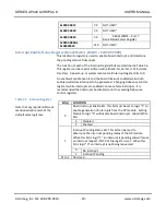
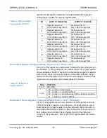
of registers. Bank 1 allows the 32 event inputs to be monitored and
controlled. Bank 2 registers control the debounce circuitry of the event
inputs. Bits 7 and 6 select the bank as follows:
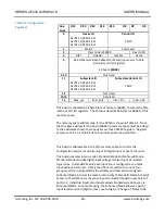
Table 3.10 Enhanced Mode
Register (Port 7)
BIT
WRITE TO REGISTER
READ FROM REGISTER
0-5
NOT USED
NOT USED
6
Bank Select Bit 0
Bank Status Bit 0
7
Bank Select Bit 1
Bank Status Bit 1
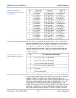
Table 3.11 Enhanced Mode
Bank Select
BIT 7 Bit 6
BANK OF REGISTERS
00
Bank 0 – Read Input Signals
01
Bank 1 – Event Status/Clear
10
Bank 2 – Event Debounce Control, Reset, and Duration
11
INVALID – DO NOT WRITE
On power-up reset, this device is placed into Standard Mode and all bits are
set to “0”.
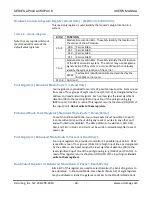
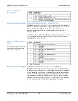
Event Sense Status & Clear Registers For IN00-IN31 (Enhanced Mode Bank 1, Ports 0-3,
Read/Write)
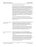
Each input line of each port includes an event sense input. Reading each
port will return the status of each input port’s sense lines. Writing ‘0’ to a bit
position of each port will clear the event on the corresponding line. When
writing ports 0-3 of Enhanced Mode bank 1, each data bit written with logic
0 clears the corresponding event sense flip/flop. Further, each data bit of
ports 0-3 must be written with a 1 to re-enable the corresponding event
sense input after it is cleared. Reading ports 0-3 of the Enhanced Mode bank
1 returns the current event sense flip/flop status.
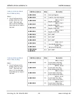
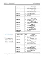
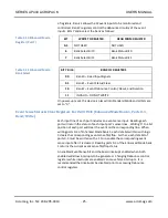
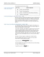
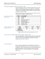
An enabled Event Sense bit and the board interrupt enabled when both
enabled will allow interrupts to be generated. Changing Debounce control
registers while interrupts are enabled can cause false interrupts. It is
recommended that interrupts be disabled prior to accessing Debounce
control registers.


