SERIES AP440 ACROPACK
USER
’S MANUAL
Acromag, Inc. Tel: 248-295-0310
- 29 - http://www.acromag.com
- 29 -
www.acromag.com
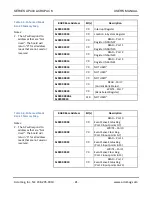
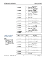
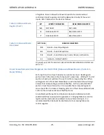
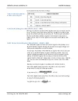
Table 3.18 Debounce Duration
Register 0:
Given the optocouplers
combined rise and fall time
typically at 50us, the debounce
settings of 3-4us and 48-64us
are not recommended for use
with the AP440.
Bit(s)
FUNCTION
1 to 0
Port 0 Debounce Value
00
3-4us
01
48-64us
10
0.75-1ms
11
6-8ms
3 to 2
Port 1 Debounce Value
00
3-4us
01
48-64us
10
0.75-1ms
11
6-8ms
5 to 4
Port 2 Debounce Value
00
3-4us
01
48-64us
10
0.75-1ms
11
6-8ms
7 to 6
Port 3 Debounce Value
00
3-4us
01
48-64us
10
0.75-1ms
11
6-8ms
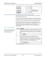
The default value is 00, setting 3-4us debounce period. This register is
cleared following a reset (setting debounce to 3-4us). Note that the
debounce clock must be reselected to re-enable debounce following a reset
(see below).
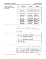
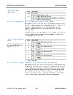
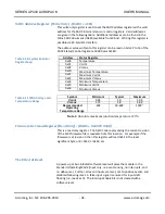
Debounce Reset Select Register (Enhanced Mode Bank 2, Port 3, Write Only)
This register bit is used to reset the debounce circuitry. If bit 0 of this
register is 0 (default value), the debounce circuitry is not reset. If bit 0 is set
to 1, then the internal debounce counters are reset. This bit should be
programmed to “1” at the start of using debounce. Bits 1-7 of this register
are not used and will always read as zero. .
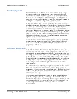
Furthermore after enabling the debounce circuitry, wait at least three times
the programmed debounce duration prior to reading the input ports or
event signals to insure valid data.
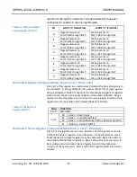
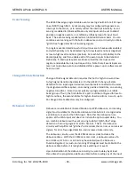
Bank Select (Write) & Status (Read) Register 2 (Enhanced Mode Bank 2, Ports 7, Read and
Write)
Bits 0-5 of this register are not used. Bits 6 & 7 of this register are used to
indicate (read) or select (write) the bank of registers to be addressed. In
Enhanced Mode, three banks (banks 0, 1, & 2) of eight registers may be
addressed. Bank 0 registers are similar to the Standard Mode bank of
registers. Bank 1 allows the 32 event inputs to be monitored and controlled.
Bank 2 registers control the debounce circuitry of the event inputs. Bits 7

