SERIES AP440 ACROPACK
USER
’S MANUAL
Acromag, Inc. Tel: 248-295-0310
- 42 - http://www.acromag.com
- 42 -
www.acromag.com
6.4 Reliability Prediction
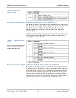
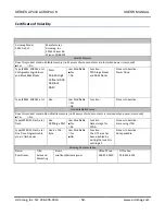
Table 6.4.1 AP440E-LF
MTBF (Mean Time Between Failure): MTBF in hours using MIL-HDBK-217F,
FN2. Per MIL-HDBK-217, Ground Benign, Controlled, G
B
G
C
Temperature MTBF (Hours)
MTBF (Years)
Failure Rate (FIT
1
)
25°C
??
??
??
40°C
??
??
??
1
FIT is Failures in 10
9
hours.
6.5 INPUTS
Input channel Configuration
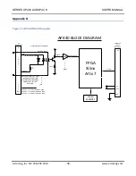
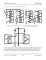
32 Optically isolated bipolar inputs. For DC or AC voltage applications within
specified range limits.
Isolation Medium
Photo-transistor optocoupler, Renesas PS2915-1 or equivalent.
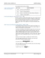
Bipolar Input Voltage Range
AC or DC Volts peak, according to model number:
4V to
18V (Model AP440-1E-LF);
16V to
40V (Model AP440-2E-LF);
38V to
60V (Model AP440-3E-LF).
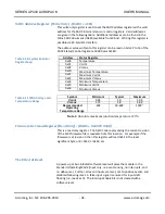
Input Threshold
Input Low-to-High threshold is:
4V Maximum,
2.0V Typical (AP440-1E-LF);
16V Maximum,
6.4V Typical (AP440-2E-LF);
38V Maximum,
12.9V Typical (AP440-3E-LF). The AP440-1E-LF model
may be used to interface with open-drain TTL outputs when used with an
appropriate pullup to +5V.
Input Hysteresis
80mV Typical
Input Capacitance
45pF Typical
Turn-On Time
Measured to the point of positive event interrupt detection - 15us Typical
(25
C) for a 0 to threshold value input step. This time increases as the
magnitude of the step is increased above the threshold.
Turn-Off Time
Measured to the point of negative event interrupt detection - 35us Typical
(25
C) for a threshold to 0V input step. This time increases as the magnitude
of the step value is increased from the threshold.
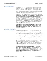
Input Debounce
Each input includes debounce circuitry with variable debounce times.
Debounce times are programmable and derived from a 31.25MHz clock, in
combination with the debounce duration register value. Debounce times
are applied at the FPGA input and do not include optocoupler delay time.
Debounce values of 3-4us, 48-64us, 0.75-1ms, and 6-8ms may be
configured.
Interrupts
32 channels of interrupts may be configured for high-to-low, low-to- high,
and change-of-state (two inputs required) event types.
Forward Voltage Drop
1.1V Typical, 1.5V Maximum (Diode) + I*R. Series input current-limiting
resistors are 1.62K (AP440-1E-LP), 10K (AP440-2E-LP), or 21.5K (AP440-3E-
LP) and installed on board.

