SERIES AP440 ACROPACK
USER
’S MANUAL
Acromag, Inc. Tel: 248-295-0310
- 32 - http://www.acromag.com
- 32 -
www.acromag.com
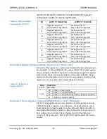
Basic Input Operation
Note that the input lines of this module are assembled in groups of eight.
Each group of eight lines is referred to as a port. Ports 0-3 control and
monitor input lines 0-31. Additionally, ports are grouped eight to a bank.
There are four banks of ports used for controlling this module (Standard
Mode, plus Enhanced Mode Banks 0, 1, and 2), plus an additional register for
enabling the interrupt request, generating a software reset.
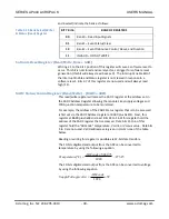
Each port input line is bipolar and accepts both positive and negative input
voltages in two ranges according to the model number. Individual input lines
of a port share a common signal connection with each other. Separate
commons are provided for each port to facilitate port-to-port isolation. A
high signal is derived from the absolute value of the input voltage measured
between the input line and the port common for the input ranges of 4-18V
(AP440-1 models), 16-40V (AP440-2 models), and 38-60V (AP440-3 models).
Inputs are non-inverting and inputs left floating (not recommended) will
register a low (false=0) input indication.
In both the Standard and Enhanced operating modes, each group of eight
parallel input lines (a port) are isolated and gated to the data bus D0..D7
lines. A high input will read as “1” and all inputs include hysteresis and
programmable debounce.
Enhanced Operating Mode
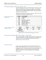
In the Enhanced Mode of operation, each port input may act as an event
sensor and generate interrupts. Likewise, programmable debounce logic is
also available. Event sensing is used to selectively sense high-to-low level, or
low-to-high level transitions on the input lines at the range thresholds of 4V
(“-1” units), 16V (“-2” units), and 38V (“-3” units). Event polarities may be
defined as positive or negative for individual nibbles (groups of 4 input lines,
or half ports). Interrupts may also be triggered by events. The optional
debounce logic can act as a filter to “glitches” or transients present on
received signals.
The Enhanced Mode is entered by writing four unique bytes to the Standard
Mode Port 7 register, in consecutive order, without doing any reads or
writes to any other port and with interrupts disabled. The data pattern to be
written is 07H, 0DH, 06H, and 12H, and this must be written immediately
after reset or power-up.
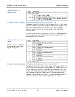
In Enhanced Mode, there are three groups (or banks) of eight registers or
ports. The first group, bank 0, provides register functionality similar to
Standard Mode (input level monitoring). The second group, bank 1, provides
monitor and control of the event sense inputs. The third group, bank 2, is
used to configure the debounce circuitry for each input while in the
Enhanced Mode.

