SERIES AP470 ACROPACK
USER
’S MANUAL
Acromag, Inc. Tel: 248-295-0310
- 15 -
http://www.acromag.com
- 15 -
www.acromag.com
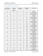
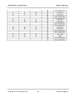
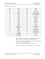
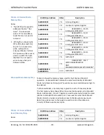
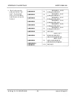
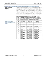
Table 2.2 Logic Interface Connections
Pin #
Name
Pin #
Name
51
+5V
1,2
52
+3.3V
3
49
+12V
1,2
50
GND
47
-12V
1,2
48
N.C. (+1.5V)
1
45
Present
4
46
N.C. (LED_WPAN#)
1
43
GND
44
N.C. (LED_WLAN#)
1
41
+3.3V
3
42
N.C. (LED_WWAN#)
1
39
+3.3V
3
40
GND
37
GND
38
N.C. (USB_D+)
1
35
GND
36
N.C. (USB_D-)
1
33
PETp0
34
GND
31
PETn0
32
SMB_DATA
29
GND
30
SMB_CLK
27
GND
28
N.C. (+1.5V)
1
25
PERp0
26
GND
23
PERn0
24
+3.3V
3
21
GND
22
PERST#
19
TDI (UIM_C4)
1
20
N.C. (W_DISABLE#)
1
17
TDO (UIM_C8)
1
18
GND
15
GND
16
N.C. (UIM_VPP)
1
13
RECLK+
14
N.C. (UIM_RESET)
1
11
REFCLK-
12
N.C (UIM_CLK)
1
9
GND
10
N.C. (UIM_DATA)
1
7
CLKREQ#
8
N.C. (UIM_PWR)
1
5
TCK (COEX2)
1
6
N.C. (+1.5V)
1
3
TMS (COEX1)
1
4
GND
1
N.C. (WAKE#)
1
2
+3.3V
3
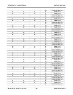
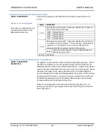
Note 1: Signals are not applicable for the AP470 implementation. Pins are
either “no connects” on the module or are repurposed for JTAG.
Note 2: +5V, +12V, and -12V power supplies have been assigned to pins that
are reserved in the mini-PCIe specification.
Note 3: All +3.3Vaux power pins are changed to +3.3V power.
Note 4: The ‘Present’ signal is tied to circuit common on the AP module.

