SERIES AP470 ACROPACK
USER
’S MANUAL
Acromag, Inc. Tel: 248-295-0310
- 18 -
http://www.acromag.com
- 18 -
www.acromag.com
This board is addressable in the PCIe memory space to control the
configuration and status monitoring of 48 digital input or output channels.
This board operates in two modes: Standard Mode and Enhanced Mode.
Standard Mode provides simple monitor and control of 48 digital I/O lines. In
Standard Mode, each input line is configured as either an input, an output,
or an output with readback capability. Data is read from or written to one of
eight groups (ports) as designated by the address and read and write signals.
A Mask Register is used to disable writes to I/O ports designated as inputs to
prevent possible contention between an external input signal and the open-
drain output circuitry. Enhanced Mode includes the same functionality of
Standard Mode, but adds access to 48 additional event sense inputs
connected to each I/O point of ports 0-5. Thus, the Enhanced Mode allows
event triggered interrupts to be generated. Selectable hardware debounce
may also be applied in Enhanced Mode for noise free edge-detection of
incoming signals.
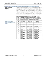
Memory is organized and addressed in separate banks of eight registers or
ports (eight ports to a bank). The Standard Mode of operation addresses the
first group of 8 registers or ports (ports 0-5 for reading/writing I/O0-47, Port
6 which is not used, and Port 7 which is the Mask Register). If the Enhanced
Mode is selected, then 3 additional banks of 8 registers are addressed to
cover the additional functionality in this mode. The first bank of the
Enhanced Mode (bank 0) is similar in operation to the Standard Mode. The
second bank (bank 1) provides event sense and interrupt control. The third
bank is used to configure the debounce circuitry to be applied to input
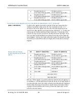
channels in the Enhanced Mode. Two additional mode-independent registers
are provided to enable the interrupt request line and generate a software
reset.
Standard (Default) Mode
Memory Map
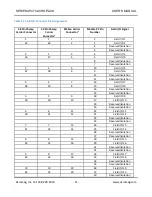
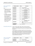
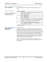
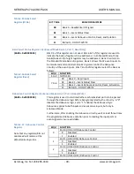
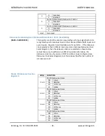
Table 3.2 shows the memory map for the Standard Mode of operation. This
is the Default mode reached after power-up or system reset. Standard
Mode provides simple monitor and control of 48 digital I/O lines. In
Standard Mode, each I/O line is configured as either an input, or an output
(with readback capability), but not both. Data is read from or written to one
of eight groups (ports), as designated by the address and read and write
signals. A Mask Register is used to disable writes to I/O ports designated as
input ports. That is, when a port (group of 8 I/O lines) is used as an input
port, writes to this port must be blocked (masked) to prevent contention
between the output circuitry and any external device driving this line.
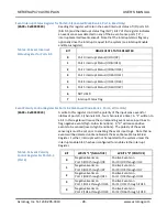
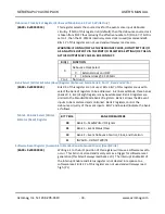
To switch to Enhanced Mode, four unique bytes must be written to port 7,
in consecutive order, without doing any reads or writes to any other port
and with interrupts disabled. The data pattern to be written is 07H, 0DH,
06H, and 12H, and this must be written after reset or power-up.

