SERIES AP470 ACROPACK
USER
’S MANUAL
Acromag, Inc. Tel: 248-295-0310
- 38 -
http://www.acromag.com
- 38 -
www.acromag.com
signals, for error-free edge detection and increased noise immunity. With
debounce, an incoming signal must be stable for the entire debounce time
before it is recognized by the I/O or event sense logic. Debounce is applied
to both inputs and event sense inputs and only in Enhanced Mode.
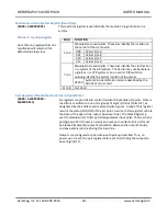
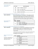
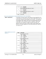
The debounce circuitry can be configured to use the 31.25MHz internal
system clock, or a clock signal present on I/O47, to determine the debounce
times (see the Debounce Clock Select register). If the debounce clock is
taken from I/O47, then the effective number of inputs is reduced to 47. If
the AP470 is configured to use the 31.25MHz internal system clock
(recommended), a debounce value of 4us, 64us, 1ms, or 8ms may be
selected (see the Debounce Duration Register). As such, an incoming signal
must be stable for the debounce time before it is recognized by the I/O pin
or event sense logic. A slower clock may be used to provide even longer
debounce times (this clock would have to be provided on I/O47).
Upon initialization of the debounce circuitry, be sure to delay at least the
programmed debounce time before reading any of the input ports or event
signals to ensure that the input data is valid prior to being used by the
software.
Interrupt Generation
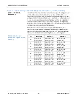
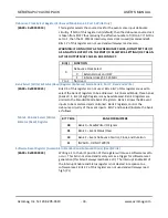
This model provides control for generation of interrupts on positive or
negative events, for all 48 channels. Interrupts are only generated in the
Enhanced Mode for event channels when enabled via the Event
Sense/Status Register. Writing 0 to the corresponding event sense bit in the
Event Sense/Status Register will clear the event sense flip/flop. Successive
interrupts will only occur if the event channel has been reset by writing a 1
to the corresponding event sense bit in the Event Sense/Status Register
(after writing 0 to clear the event sense flip/flop). Interrupts may be
reflected internally and reported by polling the module. Control of this line is
initiated via bit 0 of the Interrupt Enable Register.
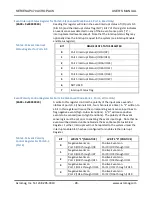
Note that the state of the inputs (on/off) can be determined by reading the
corresponding port address while in bank 0 of the Enhanced Mode.
However, the event sense status can only be read by reading the
corresponding port address while in bank 1 of the Enhanced Mode.
Remember, the event sense status is a flag that is raised when a specific
positive or negative transition has occurred for a given I/O point, while the
state refers to its current level.
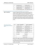
Enabling both an Event Sense bit and the board interrupts will allow
interrupts to be generated. Changing Debounce control registers while
interrupts are enabled can cause false interrupts. It is recommended that
interrupts be disabled prior to accessing Debounce control registers.
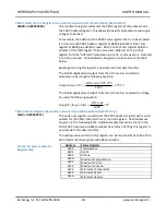
Note that the Interrupt Enable Register is cleared following a power-up or
bus initiated hardware reset, but not a software reset initiated via writing a
one to bit 1 of the Software Reset Register. Keep this in mind when you wish
to preserve the information in these two registers following a reset.

