SERIES AP220 / AP231 ACROPACK
USER
’S MANUAL
Acromag, Inc. Tel: 248-295-0310
- 19 -
http://www.acromag.com
- 19 -
https://www.acromag.com
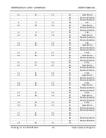
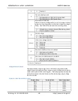
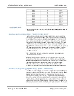
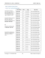
0010
Update DAC register from input register
(Updates
DAC output voltage). Software equivalent of LDAC
0011
Write and update DAC register
(Updates the input
register and DAC register irrespective of LDAC) Use
for transparent mode
0100
Write to control register
0101 No operation
0110 No operation
0111
Software data reset
(Reset to zero scale, midscale, or
full scale as specified by PV1 and PV0 bits of control.)
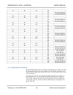
1000 Reserved
1001
Disable daisy-chain functionality
(Default enabled)
Leave enabled for SDO read-back operation.
1010
Readback input register
(Provides contents of input
register after issue of two commands and 1.6µs.)
1011
Readback DAC register
(Provides contents of DAC
register after issue of two commands and 1.6µs.)
1100
Readback control register
(Provides contents of
control register after issue of two commands and
1.6µs. See Table 3.6 for description of DAC Control
register.)
1101 No operation
1110 No operation
1111
Software full reset
(Device set to power up state,
output at AGND and output buffer is powered down.)
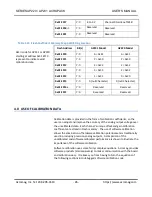
20
0 (This bit must be fixed at 0)
31 to 21
Not Used
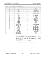
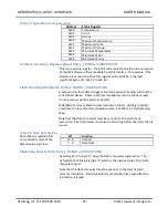
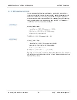
Table 3.5 DAC Channel Control Register
Bit(s)
FUNCTION
2 to 0
3-bits Output Range (Software full reset is also issued when
the output range is reconfigured.)
000
-10V to +10V
001
0V to +10V
010
-5V to +5V
011
0V to +5V
100
-2.5V to +7.5V
101
-3V to +3V
110
0V to 16V (external power supply, contact Acromag)
111
0V to 20V (external power supply, contact Acromag)
4 to 3
2-bits Power-up Voltage
00
Zero scale
01
Midscale
10
Full scale
11
Full scale

