SERIES AP220 / AP231 ACROPACK
USER
’S MANUAL
Acromag, Inc. Tel: 248-295-0310
- 21 -
http://www.acromag.com
- 21 -
https://www.acromag.com
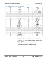
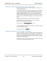
1001
+1
0001
1000
0
0000
0111
-1
1111
0110
-2
1110
0101
-3
1101
0100
-4
1100
0011
-5
1011
0010
-6
1010
0001
-7
1001
0000
-8
1000
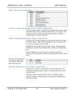
Transparent Mode
The Transparent Mode is available with DAC
Write and update DAC register
command 0011.
Simultaneous Mode (Read/Write) - (BAR0 + 0x0000 0048)
The Simultaneous Mode is a write-only register that is used to select the
simultaneous type of data transfer. Once Simultaneous Mode is selected,
digital data written should use
Write to input register
DAC Command 0001
to the address
specific channel’s in
put latch. Data will not show up at the
output until the Simultaneous Output Trigger register is written. The data,
of all the channels, is simultaneously transferred,
once per
simultaneous
trigger,
from the DAC input latch to the output (and analog output) updated
only when the Simultaneous Output Trigger register is enabled. The data
written to this location must have bit-
0 set to logic ‘1’ in order to select
Simultaneous Mode.
RESET CONDITION: Defaults to Simultaneous Mode. All analog output
channels are set to "0 Volts".
Note:
The reset function resets only the DAC output latch of the input
double buffer. Therefore, after a reset, good data must be written (using
Write to input register
DAC Command 0001) to all the input latches before
enabling the Simultaneous Output Trigger for a DAC output update.
Otherwise, old or unknown data present in the input latches will be
transferred to the DAC output latch producing an undesired analog output.
Simultaneous Output Trigger (Write Only) - (BAR0 + 0x0000 004C)
Simultaneous Output Trigger is a write-only register that produces the pulse
needed to trigger simultaneous data transfer. Simultaneous Output Trigger
register works in conjunction with the Simultaneous Mode register to
simultaneously transfer all the cha
nnels’ digital data from the DAC
input
latch to the output latch (and update the analog output) at a specific time.
The Simultaneous Mode register must be written to first. Then, writing to
the Simultaneous Output Trigger register creates the trigger for digital data
to be converted and transferred to the board’s field connector. The digital


