


AcroPack Series APCe7012E-LF
PCI Express Carrier Board
- 11 -
FIELD GROUNDING CONSIDERATIONS
The Field I/O signals are isolated from chassis and system ground on the
carrier. However, some non-isolated AcroPack modules connect Field I/O
ground to system ground. Care should be taken in designing installations
without isolation to avoid ground loops and noise pickup. This is particularly
important for analog I/O applications when a high level of accuracy/resolution
is needed (12-bits or more). Contact your Acromag representative for
information on our many isolated signal conditioning products that could be
used to interface to the AcroPack input/output modules.
CONNECTORS
The APCe7012E-LF carrier uses an AcroPack module field I/O connector, a
mini-PCIe connector, a field I/O Champ connector and one PCI Express bus
interface connector. These are discussed in the following sections.
Front Panel Field I/O Connectors
Field I/O connections are made via a 68 pin 0.8 mm Champ cable connector
mounted on the front panel. The cable and termination panel (or user defined
terminations) can be quickly mated to the field I/O connector. Pin
assignments are defined by the installed AcroPack module.
AcroPack Field I/O Connector
The field side connector of AcroPack module mates to a Samtec
SS5-50-3.00-L-D-K-TR socket connector P2 on the carrier board.
This provides excellent connection integrity due to the gold plating in the
mating area. M2.5 screws and spacers provide additional stability for harsh
environments.
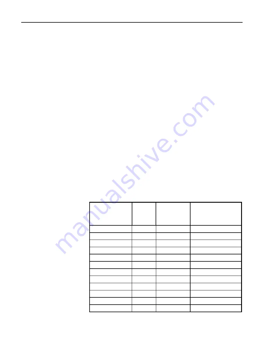
The functions of each of the Field I/O signals are defined by the installed
AcroPack model.
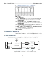
Table 3 Field I/O Pin Assignments
Carrier
J2 and Termination
Panel
Carrier
P2
Module Pin
Number
Field I/O Signal
1
2
2
Field I/O 1
35
1
1
Field I/O 2
4
4
Reserved/isolation
3
3
Reserved/isolation
2
6
6
Field I/O 3
36
5
5
Field I/O 4
8
8
Reserved/isolation
7
7
Reserved/isolation
3
10
10
Field I/O 5
37
9
9
Field I/O 6
12
12
Reserved/isolation
11
11
Reserved/isolation


