AcroPack Series APCe7012E-LF
PCI Express Carrier Board
- 8 -
BOARD CONFIGURATION
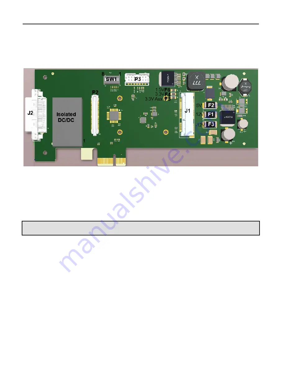
Power should be removed from the board when changing configurations,
changing/removing fuses, or when installing AcroPack modules, cables and
field wiring.
Figure 1 Connector, Switch, and Fuse Locations
Power and Cooling Considerations
Refer to the specifications for loading and power requirements. Be sure that
the system power supplies are able to accommodate the power requirements
of the carrier board, plus the installed AcroPack modules within the voltage
tolerances specified.
IMPORTANT: Adequate air circulation must be provided to prevent a temperature rise above the maximum
operating temperature.
The lack of air circulation within the computer chassis could be a cause for
some concern. Most, if not all computer chassis do not provide a fan for
cooling of add-in boards. The dense packing of the AcroPack modules to the
carrier board alone results in elevated module and carrier board
temperatures, and the restricted air flow within the chassis aggravates this
problem. Adequate air circulation must be provided to prevent a temperature
rise above the maximum operating temperature and to prolong the life of the
electronics. If the installation is in an industrial environment and the board is
exposed to environmental air, careful consideration should be given to air-
filtering.


