AcroPack Series APCe7012E-LF
PCI Express Carrier Board
- 9 -
Carrier Fuses
CAUTION: Acromag has used pins labeled as reserved in the Mini-PCIe specification for additional power
connections. If you are installing a Mini-PCIe card from another manufacturer remove fuses F1, F2 and F3.
Other fuse present on the board i1.5V fuse F6. Also present on the
board is +3.3V fuse F4. These fuses are not user replaceable. Return the
carrier board to Acromag to replace these fuses. Both Mini-PCIe cards from
other manufacturers and the AcroPack modules can use +1.5V and +3.3V
power.
Fuse not present on the board 3.3V Aux Fuses F5. Some standard
Mini PCIe cards may r3.3V Aux to power the module. For a site using
such a module the +3.3V fuse will need to be remove and the +3.3 Aux fuse
will need to be installed. Return the carrier board to Acromag to remove and
install these fuses.
Isolation Considerations
WARNING:
This AcroPack carrier is designed to provide isolation between the
AcroPack Field I/O signals and the host. The AcroPack module must also be
an isolated AcroPack module to maintain the isolation between the logic and
field I/O signals. Unless isolation is provided on the AcroPack module itself,
the field I/O connections are not isolated from the PCIe bus.
Isolated Power
The use of an optional isolated DC/DC Converter is required for use with a few
of Acromag’s isolated AcroPack modules. See Figure 1 for carrier board
location allocated for the isolated DC/DC converter.
The power supplies of one AcroPack site must be isolated from the power
supplies of other AcroPack sites. The separate isolated DC/DC converter
make this possible. The DC/DC converted should only be populated on the
carrier for an AcroPack needing the isolated power. Each isolated AcroPack
module will list the requirement of the external DC/DC converter if needed.
The isolated DC/DC converter provide dual +12V and -12V power to the
AcroPack module on field I/O pins 49 and 50 as listed in the Table below.
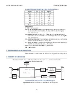
Table 1 Carrier Isolated Power
Supply Voltage
Current (Min)
Field I/O Pin
+12V
+/- 8% (max)
0.16 A
50
1
-12V
+/- 8% (max)
0.16 A
49
1
Return (GND)
1 A
48
1
Note 1:
AcroPack carriers without provisions for the isolated power supplies
can provide external power from the field power to the AcroPack module on
pins 48, 49 and 50.
CARRIER ADDRESS ASSIGNMENT
Following are the instructions for setting the slot address of the carrier. By
assigning a unique address to each carrier, system software can distinguish
this carrier from other similarly configured carriers installed in a system.
Figure 2 below shows the location of switch SW1. Set the switch state as


