Series AVME9125 VMEbus 6U Analog Input Board
___________________________________________________________________________________________
- 7 -
Card Identification Space - (Read Only, 32 Odd-Byte
Addresses)
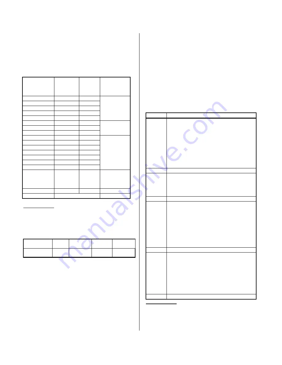
The AVME9125 contains 32 identification bytes. This
information includes the "VMEID" identifier, “ACR” manufacturer's
identification code, and board model number. Identification bytes
are addressed using only the odd addresses in a 64-byte block.
The Identification contents are shown in Table 3.2.
Table 3.2: AVME9125 Identification Bytes
Hex Offset
From Base
Address
(Hex)
ASCII
Character
Equivalent
D7-D0
Numeric
Value
(Hex)
Field
Description
01
V
56
03
M
4D
05
E
45
‘VMEID’
07
I
49
09
D
44
0B
A
41
Manufacturers
0D
C
43
ID ‘ACR’
0F
R
52
for Acromag
11
9
39
13
1
31
15
2
32
Card
17
5
35
Model
19
20
Number
1B
20
1D
20
1F
1
31
Number of
KILOBYTES of
address
space
1
21
20
23 to 3F
Undefined
Reserved
Notes (Table 3.1):
1. The board uses 256 bytes of address space.
Board Status Register - (Read/Write, Base + 40H)
The Board Status Register reflects and controls functions
globally on the board.
MSB
D15 to D4
D3
D2
D1
LSB
D0
Not Used
Soft
Reset
Not Used
Global Int.
Pending
EXP9125
Present
Where:
Bits 7, 6, 5, 4
Not used - equal "0" if read
Bit 3
Software Reset
(Write)
Writing a "1" to this bit causes a
software reset. Writing "0" or reading
the bit has no effect. The effect of
software reset on the various registers
is noted in the description of each
register.
Reset Condition: Set to "0".
Bit 2
Not used - equal "0" if read
Bit 1
Global Interrupt
Pending (GIP)
(Read)
This bit will be "1" when there is an
interrupt pending. This bit will be "0"
when there is no interrupt pending.
Polling this bit will reflect the board's
pending interrupt status, even if the
Global Interrupt Enable bit is set to "0".
Reset condition: Set to "0".
Bit 0
EXP9125 Board
Present Status
(Read)
This bit will be "1" when the EXP9125
Expander board is present in a slot
adjacent to the AVME9125. A set bit
indicates that 32 analog input ports are
available. This bit will be "0" when the
EXP9125 is not present adjacent to the
AVME9125. A zero bit indicates that
16 analog ports are available.
Control Register, (Read/Write) - (Base + 42H)
This read/write register is used to: select the interrupt request
level, acquisition input source, scan mode, enable/disable the
timer, and select the interrupt mode.
Table 3.3: Control Register
BIT
FUNCTION
0 to 2
These bits control the VMEbus interrupt request
level associated with the interrupt requests as
illustrated in the following.
000 = No Interrupt Level
001 = Interrupt Level 1
010 = Interrupt Level 2
011 = Interrupt Level 3
100 = Interrupt Level 4
101 = Interrupt Level 5
110 = Interrupt Level 6
111 = Interrupt Level 7
3
Used Internally; Leave Set to ‘0’
5,4
Acquisition Input Source
00 = All Channels Differential Input
01 = 9.79V Calibration Voltage Input
10 = Auto Zero Calibration Voltage Input
11 = Expander Auto Zero Calibration Voltage
7,6
Used Internally; Leave Set to ‘00’
10,9,8
Scan Mode
000 = Disable
001 = Uniform Continuous
010 = Uniform Single
011 = Burst Continuous
100 = Burst Single
101 = Convert on External Trigger Only
110, 111 = Not Used
See the Modes of Operation section for a
description of each of these scan modes.
11
Timer Enable 0 = Disable 1 = Enable
13,12
Interrupt Control
00, 11 = Disable Interrupts
01 = Enable Interrupt After Convert of Each
Channel
10 = Enable Interrupt After Conversion of all
selected channels is completed. A group of
channels includes all channels from the Start
Channel up to and including the End Channel
value.
14,15
Not Used
1
Notes (Table 3.3):
1. All bits labeled “Not Used” will return on a read access the last
value written.
Artisan Technology Group - Quality Instrumentation ... Guaranteed | (888) 88-SOURCE | www.artisantg.com


