


AXM-
A75 User’s Manual
Multifunction I/O Mezzanine Board
_____________________________________________________________________________________
- 16 -
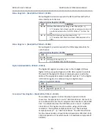
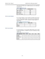
Status Register 0 - (Read/Write, P 8104H)
Status Register 0 provides access to the FIFO overflow and half full
status bits for each channel.
Table 3-5 Status Register 0 8104H
BIT
FUNCTION
31- 16
FIFO overflow interrupt pending / clear channel [16 .. 1]
A
‘1’ indicates that at least one A/D sample was lost
due to
an attempted write to a full FIFO.
Write a ‘1’ to clear the
bit.
15 - 0
FIFO half full interrupt pending channel [16 .. 1]
A ‘1’ indicates that
there are at least 1024 samples in the
FIFO.
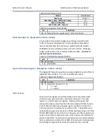
Status Register 1 - (Read/Write, P 8108H)
Status Register 1 provides access to the FIFO empty status bits for
each channel.
Table 3-6 Status Register 1 8108H
BIT
FUNCTION
31
–
16
Unused
15
–
0
FIFO empty channel [16 .. 1]
A ‘1’ indicates that the FIFO is empty.
Digital I/O (Read/Write, P 810CH)
The Digital I/O register provides access to the 16 digital I/O lines.
Digital I/O lines are pulled high via a 4.75K Ohm resistor to +5 Volts.
The levels of the digital I/O lines are returned upon a read to this
address.
The appropriate output enable bit must be ‘1’ in the
Digital
I/O Direction register to enable writing to a digital output.
Table 3-7 Digital I/O 810CH
BIT
FUNCTION
31 - 16
unused
15 - 0
Digital I/O signals [15 .. 0]
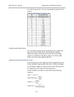
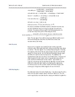
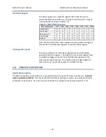
Conversion Timer Register - (Read/Write, P 8110H)
This read/write register controls the sample period of all A/D
converters. Sample period = count * ADC Clock Period. Set count to
zero to allow A/D converters to sample at their maximum rate of 500
KHz. For sample rates less than 500 KHz, enter a count > 2 µS/ADC
Clock Period. This register must be written using a 32 bit write
command. The minimum sample period is 2 µS. The maximum
sample period is (2
32
- 1) * ADC Clock Period. The ADC Clock Period
for the various models is shown Table 3-8 (exception: XMC-SLX-150(-
1M) clock period in 20 ns which results in a maximum sample rate of
420 KHz) .


