AXM-
A75 User’s Manual
Multifunction I/O Mezzanine Board
_____________________________________________________________________________________
- 19 -
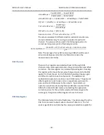
to correct for gain errors. There is a separate gain register for each
channel.
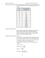
Table 3-13 Gain Register Number Format
BIT
Binary Fixed Point
31 - 17
(unused, read as 0)
16
1
15
1/2
14
1/4
13
1/8
12
1/16
11
1/32
10
1/64
9
1/128
8
1/256
7
1/1024
6
1/2048
5
1/4096
4
1/8192
3
1/16536
2
1/32768
1
1/65536
0
1/131072
Uncalibrated ADC Performance
The uncalibrated analog input channel performance is affected by
four error sources. These are the instrumentation amplifier,
difference amplifier, ADC reference and the ADC. Each of these
devices can contribute to the offset and gain error of the system.
These errors can be corrected by calibration.
Analog Input Channel Calibration Procedure
Accurate calibration of the analog input channel digitized values can
be accomplished by applying external precision calibration voltages.
The calibration voltages are used to find two points that determine
the straight line characteristic of the analog channel.
Factory calibration constants are calculated using the following
equations.
𝐺𝑎𝑖𝑛 = 1, 2, 4 𝑜𝑟 8
𝐹𝑢𝑙𝑙𝑆𝑐𝑎𝑙𝑒𝑅𝑎𝑛𝑔𝑒 =
20.48
𝐺𝑎𝑖𝑛
𝐼𝑑𝑒𝑎𝑙𝑍𝑒𝑟𝑜 =
−10.24
𝐺𝑎𝑖𝑛
𝐼𝑑𝑒𝑎𝑙𝑆𝑙𝑜𝑝𝑒 =
2
16
𝐹𝑢𝑙𝑙𝑆𝑐𝑎𝑙𝑒𝑅𝑎𝑛𝑔𝑒


