


AXM-
A75 User’s Manual
Multifunction I/O Mezzanine Board
_____________________________________________________________________________________
- 21 -
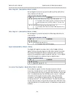
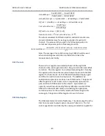
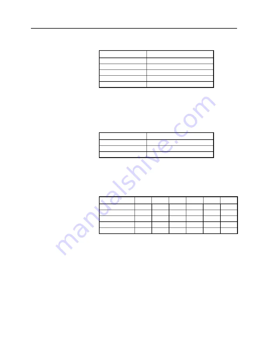
each channel (See Table 3-4). The FSR choices are ±10, ±10.2564 and
±10.5263 Volts.
Table 3-14 DAC Data Format
Volts
DIGITAL OUTPUT
+FSR * 32767/32768
FFFF
+FSR * 1/32767
8001
Midscale (zero)
8000
-FSR * 1/32767
7FFF
-FSR * 32767/32768
0000
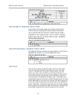
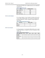
DAC Coarse Gain Register
The coarse gain register is a two bit register that allows the selection
of one of three Full Scale Ranges: ±10, ±10.2564 and ±10.5263 Volts
as shown in Table 3-15. There is a separate coarse gain register for
each channel.
Table 3-15 DAC Coarse Gain Selections
FSR Volts
Register Value
±10
0
±10.2564
1
±10.5263
2
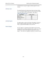
DAC Fine Gain Register
The fine gain register is a six bit register that allows the user to adjust
the gain of each DAC
by −32 LSBs to +31 LSBs in 1 LSB steps, as shown
in Table 3-16.
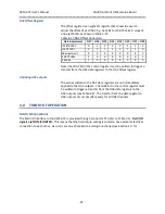
Table 3-16 DAC Fine Gain Selections
Gain Adjustment
FG5
FG4
FG3
FG2
FG1
FG0
+31 LSBs
0
1
1
1
1
1
+30 LSBs
0
1
1
1
1
0
No adjustment
0
0
0
0
0
0
-30 LSBs
1
0
0
0
0
1
-31 LSBs
1
0
0
0
0
0


