background image


BusWorks® XT Series 
10/100MB Industrial Ethernet I/O Modules 
USB Programmable, Modbus TCP/IP I/O 


Model XT1531‐000


Combination Analog Current Output and Digital I/O 
(4 DC Current Outputs and 4 Digital Inputs w/ 
4 Tandem 

High‐Side Switch Outputs)


USER’S MANUAL


ACROMAG INCORPORATED 

Tel: (248) 

295‐0880


30765 South Wixom Road 

email: sales@acromag.com 

Wixom, MI 

48393‐2417

 U.S.A. 


Copyright 2015, Acromag, Inc., Printed in the USA. 
Data and specifications are subject to change without notice. 

8501012H 

Summary of Contents for BusWorks XT Series

Page 1: ...Output and Digital I O 4 DC Current Outputs and 4 Digital Inputs w 4 Tandem High Side Switch Outputs USER S MANUAL ACROMAG INCORPORATED Tel 248 295 0880 30765 South Wixom Road email sales acromag com Wixom MI 48393 2417 U S A Copyright 2015 Acromag Inc Printed in the USA Data and specifications are subject to change without notice 8501012H ...

Page 2: ...ut Connections 9 Digital Input Connections 12 EMI Filter Installation 13 Earth Ground Connections 14 CONFIGURATION SOFTWARE 14 Quick Overview 15 CONFIGURATION STEP BY STEP 18 Getting Connected 18 Device Communication Setup 19 I O Config Test Page 22 Calibration Page 25 i2o Mapping Page 27 Network Home Page 30 BLOCK DIAGRAM 31 How It Works 31 About Modbus TCP IP 32 IP Addressing 33 Dynamic Host Con...

Page 3: ...TY CONSIDERATIONS You must consider the possible negative effects of power wiring component sensor or software failure in the design of any type of control or monitoring system This is very important where property loss or human life is involved It is important that you perform satisfactory overall system design and it is agreed between you and Acromag that this is your responsibility The informat...

Page 4: ...t ports w Auto Negotiation offers a convenient daisy chain network connection saving switch ports Operation Diagnostic LED indicators aide trouble shooting Bus Power Ready for Clean Wiring along the DIN Rail and or for Redundant Power Connection High 1500VAC Isolation between output channels combined as a group the network and power Outputs Digital I O power network and USB ports are all transient...

Page 5: ...place To remove it from the DIN rail first separate the input terminal blocks from the bottom side of the module to create a clearance to the DIN mounting area You can use a screwdriver to pry the pluggable terminals out of their sockets Next while holding the module in place from above insert a screwdriver along the bottom side path of the module to the DIN rail clip and use it as a lever to forc...

Page 6: ... AWG 2 08 0 13mm2 solid or stranded wire with a minimum temperature rating of 85o C Input wiring may be shielded or unshielded type Twisted pair or shielded twisted pair input wiring is recommended Terminals are pluggable and can be removed from their sockets by prying outward from the top with a flat head screwdriver blade Strip back wire insulation 0 25 inch on each lead and insert the wire ends...

Page 7: ...ing below Observe proper polarity input power is reverse polarity protected Optionally the unit may be powered or redundantly powered via its DIN rail connector optional terminal required see bottom figure below For supply connections use 14 AWG wire rated for at least 80 C Do not exceed 36V DC peak Note that output channels of this model will require separate connections to power see Output Conne...

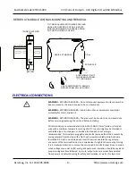
Page 8: ...ES MAY INTERCONNECT TO SHARE A POWER CONNECTION BETWEEN MODULES BUSWORKS XT BUSWORKS XT BUSWORKS XT BUSWORKS XT DIN Rail Bus Connector Acromag 1005 063 FEMALE 1005 220 DC 35mm DIN Rail MALE 1005 221 DC LEFT SIDE CONNECTOR SHIPS WITH MODULE RIGHT SIDE CONNECTOR USB Connection WARNING The intent of mating USB with this unit is so that it can be conveniently setup and configured in a safe area then i...

Page 9: ...BusWorks Model XT1531 000 4 CH Current Output 4 CH Digital I O w USB Modbus Acromag Inc Tel 248 295 0880 9 https www acromag com r e q u i r e s s e p a r a t e c o n n e c t i o n t o D C p o w e r ...

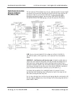
Page 10: ...OLATOR 1 ea Model XT CONFIG CDROM Software 1 ea Model 5035 360 Ethernet Cable MODEL NO USB ISOLATOR Output Connections Unit Requires Additional Connection to Power to Operate the Outputs These models control four channels each of DC current outputs and sourcing digital outputs both of which require additional excitation or separate connections to power Observe proper polarity when making output an...

Page 11: ...TURN TO EARTH GROUND THE CURRENT OUTPUTS CAN DRIVE UP TO 22 2mA INTO 550 OHMS 16 BIT OUTPUT IS 5 5253 249 22 1901mA MAX at 32767 0 20mA OUTPUT 0 to 29533 IS NORMALIZED TO 0 30000 OR 0 TO 20000 WITH LEGACY SUPPORT ENABLED 4 20mA IS A SUB RANGE OF 0 20mA 5907 TO 29533 AND IS NORMALIZED TO 0 30000 OR 0 20000 WITH LEGACY SUPPORT ENABLED THE 0 20mA NORMALIZED 0 30K MAX CURRENT IS 21 845mA 32767 THE 0 2...

Page 12: ...w USB Modbus Acromag Inc Tel 248 295 0880 12 https www acromag com WILL RESULT You can optionally use the second analog excitation terminals to connect redundant backup excitation if required but you must observe the proper voltage level for the particular terminal ...

Page 13: ...iver is also powered from the excitation supply IMPORTANT Add Protection with Inductive Loads Outputs do include internal reverse bias shunt diodes to help protect the output switch from damage due to high reverse bias voltages generated when switching inductive loads But you should add external protection near the inductive load to prevent these transients from being sent along the connection wir...

Page 14: ...K pull down resistors installed on the board and will never float Observe proper polarity when making I O connections Refer to the following figures to wire the digital inputs of this model IMPORTANT You must keep the tandem output turned off when using the input to sense voltage levels from the field to prevent contention between the field signal and the output channel which may be turned ON If y...

Page 15: ...nd Power order Acromag 4001 135 Laird 28A0592 0A2 or similar for USB cable Acromag 4001 140 and Laird 28A0807592 0A2 or similar for Ethernet cable Acromag 4001 139 Locate ferrites by clamping them outside of all I O cables or wiring harnesses to from the module USB Ethernet input output group DC power and as close to the module as possible While the use of these ferrites ishelpful to obtain low CE...

Page 16: ...rounds its USB port and this makes contact with both the USB signal and shield ground which is held in common to the input circuit return of this module CONFIGURATION SOFTWARE While this is an Ethernet network I O module it can only be configured and calibrated via its Configuration Software over a USB connection to a Windows based PC or laptop USB saves you the trouble of having to already know i...

Page 17: ...up Device Select First Connect to the Unit Here Select from connected modules and Open or Close communication with them Display the Model Serial Number and Manufacturer of the connected module and report the status of the USB connection Reboot a module to force a system reset to the power up state Restore a module to its initial out of box state Ethernet Setup Setup your Network Parameters Retriev...

Page 18: ...orce a restart following thermal shutdown digital outputs You can even choose to invert the logic for the tandem digital input channel useful for i2o operation Choose Legacy Support Yes if you want the output to scale 0 100 to 0 20000 versus 0 100 to 0 30000 Optionally invert the Input Logic of digital input channels Check Support Coil Register versus Holding Register to enable write digital outpu...

Page 19: ...e the output range zero or full scale signal and enter the measured value here i2o Mapping This model includes a special remote messaging function called i2o for input to output communication with respect to its digital input channels This allows it to send its digital input information over the network to digital outputs on another unit or compatible unit without having to hard wire a connection ...

Page 20: ... connection to excitation is required 4 Connect Power You need to connect power from 12 32V to power this module Current required will vary with voltage level refer to Specifications Your supply must be capable of providing at least twice the maximum rated current for your voltage level You can choose to connect to Power via terminals on the unit or via optional terminals that connect to the modul...

Page 21: ...elow After clicking Open the selected unit s Model Serial Number Manufacturer and a connection status message will be displayed as shown in the second screen at left TIP Always Close a connection with one device before selecting another device You can use the Reboot Module button to force a reset of the unit by clicking on it an effect equivalent to a power on reset You can use the Restore Module ...

Page 22: ...mber for any host this module on any TCP IP network including the internet It uniquely defines one host from all other computers hosts on the Internet The IP address is made up of four octets 8 bits each octet having a value between 0 255 00H FFH It is expressed here in decimal form with a period between octets The Subnet Mask is used to subdivide the host portion of the IP address into two or mor...

Page 23: ...models required it is not available for Modbus TCP IP models In this method the TCP IP object of the particular protocol for Ethernet IP sets the address Profinet requires protocol addressing and has its own method for accomplishing address assignment using this method By default the module is setup to use Static IP Addressing and a default Static IP Address of 192 168 1 100 You can optionally cho...

Page 24: ...en click Send Config to write the channel configuration to the unit or more simply make changes to many channels and then click Send Config one time to write all the channel configurations to the unit Select the Range Use the Range field to select your output range analog channels only For the XT1531 000 model you can select a DC Current Output range of 0 20mA or 4 20mA at each of four analog outp...

Page 25: ...tire I O configuration to the device You can choose to do this one time after you have setup all the I O channels individually Once you have made your configuration selections click the Send Config button to write them to the module You can read the USB Status of your sent configuration message to the unit in the Status field just above the Send Config button Alternately you could click File in th...

Page 26: ...s Note the simulated green lamp next to the Start Polling button flashes slowly each time it samples the input Click Stop Polling to stop polling the inputs before moving onto the next page Start Polling Button Toggle Start Stop Click this button to Start Stop periodic polling of the digital input channels The channel states are indicated via 1 0 and LED color and updated about once per second Be ...

Page 27: ...r 30 seconds of slide or arrow inactivity Simply set the output to precisely 1mA using a meter to measure the output a live zero is used instead of 0mA to improve the accuracy of calibration click the zero button then OK to set the zero endpoint Repeat this at 20mA using the full scale button CAUTION The controls of this page will temporarily change the output signal level slide control uses a 30 ...

Page 28: ...ke No Error Transfer Error and Timeout Error after clicking OK during calibration If you encounter a Transfer or Timeout Error you may have to repeat the calibration process HELP You can press F1 for Help on a selected or highlighted field or control You can also click the button in the upper right hand corner of the screen and click to point to a field or control to get a Help message pertaining ...

Page 29: ...l input channel s data to either upon change of state and or cyclically at the update time specified IMPORTANT i2o refers to an Acromag proprietary method of input to output communication done over the network without other hard wired connections between inputs and outputs This is not a Modbus TCP IP function and the i2o mapping feature of this model may only be configured via this software As suc...

Page 30: ...ule but may take several minutes to discover the network targets and begin transmitting to them If this input module or the target module s go offline remote i2o messaging will resume on its own when the connection is re established but this healing function may take several minutes depending on which device s went offline why and for how long It is not recommended to set an i2o update rate greate...

Page 31: ...econds between messages Specify 0 or 65535 to turn i2o messaging OFF cyclical If change of state is enabled and a time greater than or equal to 5 is specified your message will be sent both upon change of state and at the update time specified Change of State Checkbox Set ON to enable output updates on change of input state and OFF to update cyclically according to the update time Keep Target Sock...

Page 32: ...ess on the Device Communication Setup page of the USB Configuration Software for the unit the default is 192 168 1 100 This will access the home page of the unit similar to the first screen shown on the following page You can click the Communication Parameters link of the Home Page to access the Ethernet Connection Status page shown in the second screen on the following page which reviews the unit...

Page 33: ...d is fed back to the controller through a 100KΩ series resistor which drives non inverting input buffers with input diodes clamped to its 3 3V rail allowing input voltages well above the rail up to 32V Digital input channels use TTL logic thresholds and feed back the actual state of the tandem output source or optionally an input state from the field with its tandem output turned OFF Network commu...

Page 34: ...r destination address in a different order While the IP delivers the data packets it is up to another protocol the TCP Transmission Control Protocol to make sure that the packets are reassembled in the correct order So we see that the function of TCP is to ensure that all packets of data are received correctly while IP makes sure that messages are correctly addressed and routed Thus TCP IP refers ...

Page 35: ...ue IP Address that is assigned by a service provider and never changes A Dynamic IP Address is an address that is temporarily assigned to a user by a service provider each time a user connects A Subnet is a contiguous string of IP addresses The first IP address in a subnet is used to identify the subnet while the last IP address in a subnet is always used as a broadcast address Addresses between t...

Page 36: ...emaining bits the host or node address For our Example if we wish to further divide this network into 14 subnets then the first 4 bits of the host address will be required to identify the subnetwork 0110 then we would use 11111111 11111111 11111111 11110000 as our subnet mask This would effectively subdivide our Class C network into 14 subnetworks of up to 14 possible nodes each With respect to th...

Page 37: ...lding Register A 4x register is used to store 16 bits of numerical data binary or decimal or to send the data from the CPU to output channel s The Reference leading character indicated above is generally implied by the function code and omitted from the address specifier for a given function The leading character also identifies the I O data type The x following the leading character represents a ...

Page 38: ...Modbus functions operate on register map registers to monitor and control module I O CODE FUNCTION REFERENCE 01 00H Read Coil Output Status 0xxxx 02 02H Read Input Status 1xxxx 03 03H Read Holding Registers 4xxxx 04 04H Read Input Registers This Model 3xxxx 05 05H Force Single Coil Output 0xxxx 06 06H Preset Single Register 4xxxx 15 0FH Force Multiple Coils Outputs 0xxxx 16 10H Preset Multiple Reg...

Page 39: ...ed The full possible range is decimal 0 109 2 or 0 32768 decimal Thus for this model 20mA is driven with a raw register DAC count of 0 to 32768 0 020 249 5 5254 29533 A 4mA range zero would correspond to 32768 0 004 249 5 5254V 5907 Register Map This model has two different register maps depending on the mode of digital output access you select That is you can enable Coil Registers and use those r...

Page 40: ...Digital Output Channel 0 State A 16 bit register that addresses the state to set the digital output to 00002 0001 Digital Output Channel 1 State A 16 bit register that addresses the state to set the digital output to 00003 0002 Digital Output Channel 2 State A 16 bit register that addresses the state to set the digital output to 00004 0003 Digital Output Channel 3 State A 16 bit register that addr...

Page 41: ... Applicable if the Coil Register Option is Disabled 40001 0 0000 Set DO State for Digital I O Channels 0 3 Bit 15 4 0 Not Used Bit 3 Digital Output CH3 Bit 2 Digital Output CH2 Bit 1 Digital Output CH1 Bit 0 Digital Output CH0 1 Turn Output ON Source Load 0 Turn Output OFF Open Setting the bit to 1 will drive the corresponding output to source excitation to the load conducts or sinks load current ...

Page 42: ... adjacent field input channels to keep them turned OFF Then use a bitmask and either OR the current setting with 1 to turn the output ON or AND the current setting with 0 to turn the output OFF as required and in the specific bit position s that correspond to the output channel s to be changed One example for accomplishing this follows The software contained here is provided only as a guide with t...

Page 43: ...tate switch channel case 0 case 4 case 8 case 12 if state OutputWord channel 4 0x0001 break else OutputWord channel 4 0x0001 case 1 case 5 case 9 case 13 if state OutputWord channel 4 0x0002 break else OutputWord channel 4 0x0002 case 2 case 6 case 10 case 14 if state OutputWord channel 4 0x0004 break else OutputWord channel 4 0x0004 case 3 case 7 case 11 case 15 if state OutputWord channel 4 0x00...

Page 44: ...BusWorks Model XT1531 000 4 CH Current Output 4 CH Digital I O w USB Modbus Acromag Inc Tel 248 295 0880 44 https www acromag com OutputWord channel 4 0x0008 ...

Page 45: ... FIRST_DO_HADDRESS Loop OutputWord Loop This method assumes that there is more than 1 master or some other entity that could possibly change the output s and reads the current output values from the device first main unsigned char Loop Read the 4 output words from the device first and store in the OutputWord variable using whatever Modbus hook you have This is just an example and your code will di...

Page 46: ...UN LED will continue to blink as the unit initially hunts for a network link Connect a network cable to the unit to allow it to complete its initialization and stop the blinking Note this only occurs for the initial network communication following power up Unit failed to boot firmware Internal Firmware Failure A continuously flashing green Run LED can signify the unit has failed to initialize and ...

Page 47: ...and re open the module for communication or simply exit the Configuration software and reboot it Cannot Communicate with Module via USB A missing USB Isolator could cause a ground loop between a grounded input signal and earth ground at the connected Personal Computer s USB port The USB isolator breaks the ground loop created between a grounded input signal source and earth ground of the PC USB po...

Page 48: ...ource output which may be ON or the Invert Input Logic function is enabled If you are monitoring a field wired digital input you must turn the channel s corresponding output OFF Check the state of the Invert Input Logic function Note that the output will turn OFF if contention with a field input signal occurs and you will have to cycle excitation OFF ON to restore output operation Digital I O Chan...

Page 49: ... the Coil Register control mode at your target i2o output module to allow its outputs to be programmed via an input holding register Wrong control mode is set at the i2o target Make sure your i2o target is using holding register control mode as opposed to coil register control mode Your target output shut down due to contention with a field input signal Contention at the I O channel triggers a pro...

Page 50: ...s lost Device Setup page Network Status field indicates Failed its current outputs go to 0mA If your Network status message indicates Failed try cycling power to the module to force a re initialization The Restore to Out of Box condition or sanitize may also recover unit operation There are a few scenarios that can drive this error condition If you are changing the configuration of an i2o target m...

Page 51: ...ries USB Isolator Order USB ISOLATOR USB Signal Isolator USB A B Cable 4001 112 Instructions 8500 900 This kit contains a USB isolator and a 1M USB A B cable for connection to a PC This isolator and cable are also included in XT SIP see above A USB isolator is recommended for program and configuration of all XT I O models USB A B Cable Order 4001 112 USB A B Cable 4001 112 This is a 1 meter USB A ...

Page 52: ... Power Two end stops 1027 222 used to secure the terminal block and module for hazardous location installations Low EMI Double Shielded Patch Cable Ethernet Patch Cable 3 feet long Model 5035 369 Ethernet Patch Cable 15 feet long Model 5035 370 This cable is used to connect a module to your network switch like an Acromag 900EN S005 or equivalent Ethernet switch and is double shielded for lower emi...

Page 53: ...tive current is pulled from the analog excitation supply sourced from the output channel and pushed through the load to Return RTN The unit must be wired and configured for the intended output see Connections section for details The following paragraphs summarize this model s analog output type ranges and applicable specifications Output Ranges Select 0 20mA DC or 4 20mA DC a sub range of 0 20mA r...

Page 54: ...e normalized count For normalization to 30000 the effective resolution is dominated by the 16 bit raw DAC resolution at 1 part in 29533 But for normalization to 20000 the effective resolution is dominated by the normalized resolution of 1 part in 20000 For the 4 20mA range and normalization to 30000 we get a maximum current of 20mA 16mA 2767 30000 21 4757mA For the 4 20mA range and normalization t...

Page 55: ...rotect the output channel from damage due to overload cycle excitation OFF ON to restore output operation after a shutdown Output Thermal Shutdown Individual outputs will shutdown and latch off for thermal overload conditions that drive the junction temperature into the region from 150 to 200 C If your outputs stop working the I O pin is pulled low and the output must be cycled OFF ON to restore o...

Page 56: ...ts OFF and you must cycle output excitation OFF ON to restore output operation Digital Inputs This model has four tandem digital input and outputchannels No additional excitation is required to operate the digital inputs as excitation is only required for output operation Always turn digital outputs OFF if only using the inputs to monitor field signals This model includes four active high buffered...

Page 57: ...than 0 001 of output span effect per volt DC change Unit includes a USB socket for temporary connection to a PC or laptop for the purpose of setup reconfiguration and trouble shooting USB isolation is recommended when connecting to a unit that may also be connected to grounded I O signals The unit does not receive power from USB and should already have DC power connected to it when connecting to U...

Page 58: ...kets 8 pin 10BaseT 100BaseTX The metal shield circuit of the network connectors is isolated and capacitively coupled to the input power minus terminal via an isolation capacitor Network to Network Isolation Network ports are additionally isolated from each other and will withstand a 1000VAC dielectric strength test for 1 minute without breakdown Wiring Unit includes auto crossover for MDI or MDI X...

Page 59: ...in this manner Shipping Weight 0 5 pounds 0 22 Kg packed These limits represent the minimum requirements of the applicable standard but this product has typically been tested to comply with higher standards in some cases Operating Temperature 40 C to 60 C 40 F to 140 F Storage Temperature 40 C to 85 C 40 F to 185 F Relative Humidity 5 to 95 non condensing Isolation I O channels analog and digital ...

Page 60: ...at is set at a level not exceeding 140 of the peak rated voltage value at the supply terminals to the equipment Reliability Prediction Configuration Controls Reliability Prediction MTBF Mean Time Between Failure MTBF in hours using MIL HDBK 217F FN2 Per MIL HDBK 217 Ground Benign Controlled GBGC XT1531 000 MTBF Hours MTBF Years Failure Rate FIT 25 C 445 034 hrs 50 8 years 2 247 40 C 335 836 hrs 38...

Page 61: ...odel REVISION HISTORY The following table shows the revision history for this document Release Date Version EGR DOC Description of Revision 26 AUG 14 A BC ARP Updated Initial Release 13 OCT 14 B BC ARP Add UL approvals removed pending per 14K010 added MTBF data 06 APR 15 C FJM ARP Shows terminals 11 and 12 with the incorrect polarity Added DIN rail ground warning per Rob Frewald 15 OCT 2015 D CAP ...

Reviews: