BusWorks Model XT1531‐000
4 CH Current 4 CH Digital I/O w/USB & Modbus
Acromag, Inc. Tel: 248‐295‐0880
‐
13
‐
Digital Output Connections
(Requires Additional
Excitation at TB6)
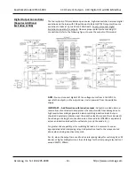
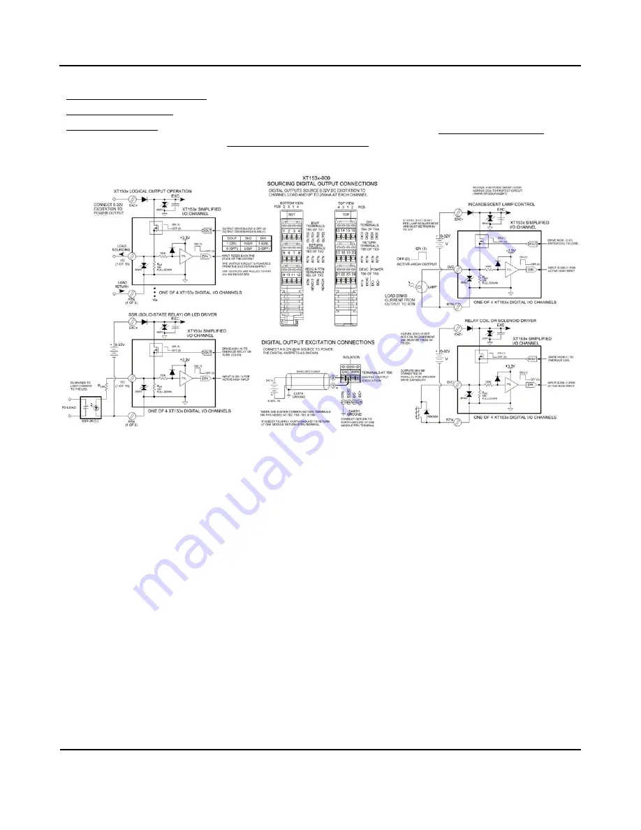
The four outputs of this model are open‐source, high‐side switches, between digital
excitation and the load, with 10K pull‐downs to Return (RTN). Outputs will source
excitation to loads at up to 32V and 250mA each. You must connect digital
Excitation to operate the outputs. Observe proper polarity when making I/O
connections. Refer to the following figures to wire the outputs of this model.
NOTE:
You must connect digital EXC to a voltage source from 6 to 32VDC to
operate the outputs, as the output driver is also powered from the excitation
supply.
IMPORTANT
–
Add Protection with Inductive Loads
: Outputs do include internal
reverse‐bias shunt diodes to help protect the output switch from damage due to
high reverse‐bias voltage
s generated when switching inductive loads. But you
should add external protection near the inductive load to prevent these transients
from being sent along the connection wires. Place a diode (1N4006 or equivalent)
across an inductive load with the cathod
e to (+) and the anode to (‐).
For greater drive capability or for switching AC loads, it is common to use an
appropriately rated interposing relay. Add protection local to the relay as noted
above when driving inductive relay coils.
Per UL, when the outputs are used to drive interposing relays for switching AC or DC
devices of higher voltage/current, the coil ratings for the interposing relay shall not
exceed 24VDC, 100mA.


