BusWorks Model XT1531‐000
4 CH Current 4 CH Digital I/O w/USB & Modbus
Acromag, Inc. Tel: 248‐295‐0880
‐
56
‐
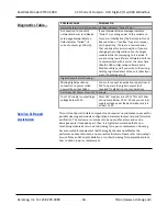
Digital Outputs…
Note:
You must connect digital
excitation to operate digital
outputs. Input only operation
does not require Excitation.
Digital Output Excitation (Required for Operation):
Excitation must be from 6‐32V
and 14mA minimum (at 32V and no load), and is applied between the digital I/O EXC
and Return (at TB6). The digital excitation current capacity should be at least 1.2A to
deliver full rated load to all four outputs. Reverse voltage protection is included.
The actual capacity of your excitation supply will depend on the loads and number of
channels being loaded. The high‐side switched outputs will source the excitation
voltage to the load when turned ON, but are also powered from it, and outputs
cannot operate without this excitation. The EXC terminal is tied in common to the
drains of each output channel switch. The source leads of each switch are pulled
down to return via 10KΩ pull‐down resistors and drive the output load. You do not
need excitation to operate the tandem digital inputs of this model, only the outputs.
Digital I/O Pull‐Downs:
Individual digital I/O channels have 10KΩ pull‐downs to
return and will never float. The installed resistor is one element of a four element
isolated SIP resistor (8 pins) and rated to 0.3W per element up to 70°C (refer to
Bourns 4308M‐102‐103LF parts). If your application requires a stronger pull‐down
(lower resistance), you will have to wire it externally in parallel with your load, being
careful that you do not exceed 250mA of source current per output (load max plus
pull‐down current).
IMPORTANT:
If you trigger the output’s protection mechanism, perhaps via
accidental contention between an output channel and a field input signal, it shuts
OFF and you must cycle output excitation OFF/ON to restore output operation.
Digital Inputs
This model has four tandem
digital input and output channels.
No additional excitation is
required to operate the digital
inputs, as excitation is only
required for output operation.
Always turn digital outputs OFF if
only using the inputs to monitor
field signals.
This model includes four active‐high, buffered inputs, with a common return
connection (RTN) for DC voltage applications only and these are used to read back
the output or field inputs. Inputs are tied in tandem to the output source leads and
provide loopback monitoring of the output state. With the tandem output turned
off, they may be used to monitor voltage levels up to 32V from the field. Inputs
include transient suppression and series connected 100K
resistors, plus diode
over‐
voltage clamps to the in3.3V supply rail. Individual I/O channels are pulled
down to the return (RTN terminal) with 10KΩ resistors. External excitation at
TB6
(the source to the load) is required for output operation and is connected between
the EXC and RTN terminals of TB6 (terminal numbers 22 and 21 respectively).
Digital Input Signal Voltage Range:
0 to +32VDC.
Digital Input Current:
280uA, typical at 32VDC. This is computed as the maximum
applied input voltage minus 4V (3.3V rail and diode clamp), divided by the series
100K
input resistance.
Digital Input Threshold:
TTL compatible w/100mV of hysteresis, typical. Low‐to‐
High threshold is 1.
7VDC, typical, High‐to‐Low threshold is 1.6VDC, typical. Logic
limits are TTL with 0.8VDC Max LOW level, and 2.0VDC Min HIGH level.
Digital Input Resistance:
10K
, typical (inputs include 10KΩ pull‐downs to return).
Digital Input Hysteresis:
100mVDC typical.
Digital Input Response Time:
10ms typical, not including network time. The actual
input response time will vary with network traffic and interrupts.
Digital Input Transient Voltage Suppressor:
Installed at every I/O point, the rated
working voltage is 38V, breakdown voltage is 47V, and clamping level is 72V.

