BusWorks Model XT1531‐000
4 CH Current 4 CH Digital I/O w/USB & Modbus
Acromag, Inc. Tel: 248‐295‐0880
‐
57
‐
Power
USB Interface
Power Supply (Connect at TB6 terminals 24 & 23, and/or via the DIN Rail Bus):
12‐
32V DC SELV (Safety Extra Low Voltage), 2.8W max. Observe proper polarity.
Reverse voltage protection is included. Unit can be redundantly powered by
connecting power to both the power terminals on the unit at TB6 and the DIN rail
bus at TB7 (these power inputs are diode‐coupled to the same point in the circuit).
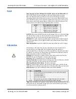
Current draw varies with power voltage as follows (this is with all outputs set full‐
scale, but does not include analog or digital excitation currents):
SUPPLY
XT153x‐000 SUPPLY CURRENT
12V
206mA Typical / 227mA Max
15V
160mA Typical / 176mA Max
24V
100mA Typical / 110mA Max
32V
76mA Typical / 84mA Max
CAUTION:
Do not exceed 36VDC peak to avoid damage to the unit. Terminal voltage
at or above 12V minimum must be maintained to the unit during operation. Most
supplies are ±10%, but this module will not operate below 11.5V.
Excitation:
This model requires a separate power connection for its digital outputs
and its analog outputs. Refer to Digital Outputs and Analog Outputs for excitation
requirements.
Power Supply Effect:
Less than
0.001% of output span effect per volt DC change.
Unit includes a USB socket for temporary connection to a PC or laptop for the
purpo
se of setup, reconfiguration, and trouble‐shooting. USB isolation is
recommended when connecting to a unit that may also be connected to grounded
I/O signals. The unit does not receive power from USB and should already have DC
power connected to it when connecting to USB.
CAUTION:
Do not attempt to connect USB in a hazardous environment. Module
should be setup and configured in a safe environment only.
Data Rate:
USB 2.0 compatible, up to full‐speed at 12Mbps.
Transient Protection:
Unit adds transient voltage protection to USB power and data
lines when connected, but the unit does not use USB power.
Cable Length/Connection Distance
: 5.0 meters maximum.
Driver:
No special drivers required. Uses the built‐in USB Human Interface Device
(HID) drivers of the Windows Operating System (Windows XP or later versions only).
USB Connector:
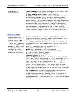
5‐pin, Mini USB B‐type socket, Hirose UX60‐MB‐5S8.
PIN
DEFINITION
1
+5V Power (Transient protected, but not used by this model)
2
Differential Data (+)
3
Differential Data (‐)
4
NC
–
Not Connected
5
1
Power Ground (Connects to Signal Ground via ferrite bead)
SHLD
1
Signal Ground (Connects directly to Signal Ground)
1
Note:
Most Host Personal Computers (except battery powered laptops) will connect
earth ground to the USB shield and signal ground, and this will drive ground loop
errors when your I/O is also grounded.
!

