Model DT233-0600
Dual Two-Wire mV/TC Input Transmitters
Acromag, Inc. Tel: 248-295-0880
- 21 -
http://www.acromag.com
- 21 -
https://www.acromag.com
TECHNICAL REFERENCE
OPERATION STEP-BY-STEP
Connections
This section will walk you through
the Connection-Configuration-
Calibration process step-by-step.
But before you attempt to
reconfigure or recalibrate this
transmitter, please make the
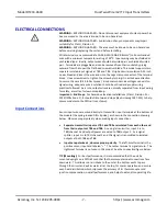
following electrical connections
Once you have made your input,
output/power, and USB
connections, and you have applied
power to your output loop(s), you
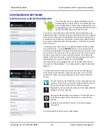
can execute the DT233Config.exe
software for this model to begin
configuration (this software is
compatible with Windows 7 or
later versions of the Windows
operating system), or you could
optionally start the Agility mobile
app (Android only).
Note:
Your input signal source, output meters, and loop load resistors for the
current output must be accurate beyond unit specifications, or better than ±0.1%.
A good rule of thumb is that equipment accuracy should be four times better than
the rated accuracy you wish to achieve.
Calibration Connections:
1.
Connect Inputs:
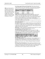
Connect a precise millivoltage source or T/C calibrator to the
TB1 (channel 1) or TB3 (channel 2) input, as required for your input type/range.
Observe proper polarity.
In the absence of a thermocouple calibrator, a convenient method of
configuring a TC input channel would be to use a precision mV source with the
channe
l’s
CJC set to OFF. This method allows the mV source to be wired
directly to the input terminals using copper wires. With t
he module’s cold
junction compensation turned off, the mV signal applied to the input is the
equivalent thermoelectric voltages that corresponds to temperatures inside
the minimum and maximum range of temperature for your T/C type. Refer to
the table on the next page for a list of supported thermocouple voltages at
specific temperatures. After setting the range zero and full-scale this way, CJC
should be returned to ON to enable cold junction compensation when the
input is wired using thermocouple wires. For best results, set the input filter as
desired before calibrating an input.
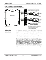
2. Connect Output/Power (each Output):
Refer to Output/Power Connection of
page 10 and wire an output current loop to the transmitter as illustrated (two
loops if you are using both channels). You will need to measure the output
current accurately at each output to calibrate the unit. You could connect a
current meter in series in each output loop to read the loop current directly
(not recommended). A better approach would be to simply connect a
voltmeter across a series connected precision load resistor in each loop, and
accurately read the output current as a function of the IR voltage drop
produced in the resistor (recommended). In any case, be sure to power each
loop with a voltage that is minimally greater than the 7V required by the
transmitter, plus the IR drop of the wiring and terminals, plus the IR drop in the
load (be sure to use a current level that considers the over-scale current as
follows: Loop Voltage= 7V+ 0.024*Rload with negligible line drop). In this
model, output channel 1 powers the unit’s microcontroller and input channel 1
while output channel 2 only powers input channel 2. Always apply power to at
least one output loop even when connected to USB.
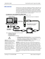
3. Connect to PC via isolated USB:
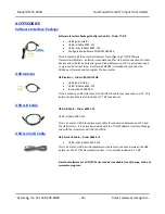
Refer to USB Connection on page 13 and
connect the transmitter to the PC using a USB isolator and cables provided in
the Configuration Kit TT-SIP. Optionally, you could instead connect the unit to
an Android smartphone or tablet running the Agility mobile app with a USB-
OTG cable.
Connect Input
Connect Output/Pwr
Connect PC/USB
Configure
Optional
Calibrate I/O

