Model DT233-0600
Dual Two-Wire mV/TC Input Transmitters
Acromag, Inc. Tel: 248-295-0880
- 37 -
http://www.acromag.com
- 37 -
https://www.acromag.com
Inputs (Each)
…
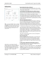
Input ranges may be rescaled to
smaller ranges to drive each 4-
20mA output and the effective
input resolution will be
proportionally diminished as you
reduce an input span below
nominal by rescaling it (you lose
1-bit every time you halve the
range). Be careful not to
diminish resolution below 12-bits
minimum (1 part in 4096) for
rated performance
Input Noise Rejection (Common Mode):
Varies with input filter selection between
no filter and high filter as follows (data measured with a 100
input unbalance):
Typical Common Mode Noise Rejection
MODEL
None
High
DT233
100dB
135dB
Input Noise Rejection (Normal Mode):
Varies with input filter level.
Typical 60Hz Rejection per Input Filter Setting
MODEL
None (dB)
Low (dB)
Med
1
(dB)
High
1
(dB)
DT233
0.5dB
20dB
> 80dB
1
> 80dB
1
1
Note:
At medium and high filter settings, the heavily attenuated 60Hz signal cannot
be measured due to 4
th
order filtering by the input ADC which adds 80dB minimum of
rejection at frequencies between 47Hz and 61Hz.
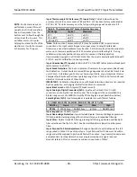
Input Resolution:
The ADC divides the signal into a number of incremental parts
calculated by subtracting endpoint A/D counts computed via (Vin*Gain/1.25)*32768
+32768, with Gain=8, 16, 32, or 64, depending on the input Type (see Table 3).
Table 3: Input Range Resolution
INPUT RANGE
xDIVIDER xGAIN RAW A/D INPUT RESOLUTION
V (-1.000V to +1.000V)
NONE
1
6554 to 58982 or 1/52428
mV (-100mV to +100mV)
NONE
8
11796 to 53740 or 1/41943
T/C J (-210 to +760°C)
(-8.095mV to 42.919mV)
NONE
16
29373 to 50770 or 1/21397
T/C K (-200 to +1372°C)
(-5.891mV to 54.886mV)
NONE
16
30297 to 55789 or 1/25492
T/C T (-260 to +400°C)
(-6.232mV to 20.872mV)
NONE
32
27540 to 50277 or 1/22736
T/C R (-50°C to +1768°C)
(-0.226mV to 21.101mV)
NONE
32
32578 to 50469 or 1/17890
T/C S (-50°C to +1768°C)
(-0.236mV to 18.693mV)
NONE
32
32570 to 48449 or 1/15879
T/C E (-200 to +1000°C)
(-8.825mV to 76.373mV)
NONE
8
30917 to 48785 or 1/17867
T/C B (+260 to 1820°C)
(0.317mV to 13.820mV)
NONE
64
33300 to 55954 or 1/22654
T/C N (-230 to +1300°C)
(-4.226mV to 47.513mV)
NONE
16
30995 to 52696 or 1/21701
CJC (-50°C to 150°C)
(0V to 1V)
NONE
1
32768 to 58983 or 1/26214
The digital count is converted to TC temperature via a linearizer function for the TC
type (the transmitter output is made linear with respect to TC temperature, not TC
voltage). This conversion resolves to 0.05C, which can limit input resolution for small
spans (for example, a span of 200°C yields a linearizer resolution of 200/0.05=4000
parts). The linearized temperature is extrapolated to the output based on a straight-
line calculation formed by mapping your specified input range endpoints to the
output range endpoints. Input ranges that have the same gain are calibrated by
extrapolating from another input range calibration. The effective I/O resolution for a
given range will be the lowest resolution of the A/D (see below), or its linearized
value (using 0.05C intervals), as D/A resolution is always greater.


