Model DT233-0600
Dual Two-Wire mV/TC Input Transmitters
Acromag, Inc. Tel: 248-295-0880
- 39 -
http://www.acromag.com
- 39 -
https://www.acromag.com
Output…
CAUTION:
Do not exceed 36VDC
peak to avoid damage to the unit.
Terminal voltage at/above 7V
minimum must be maintained
across the output during
operation.
Compute R
load
(Max) =
(V
supply
- 7V)/0.021A for 21mA
output current. Refer to the table
at right.
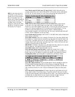
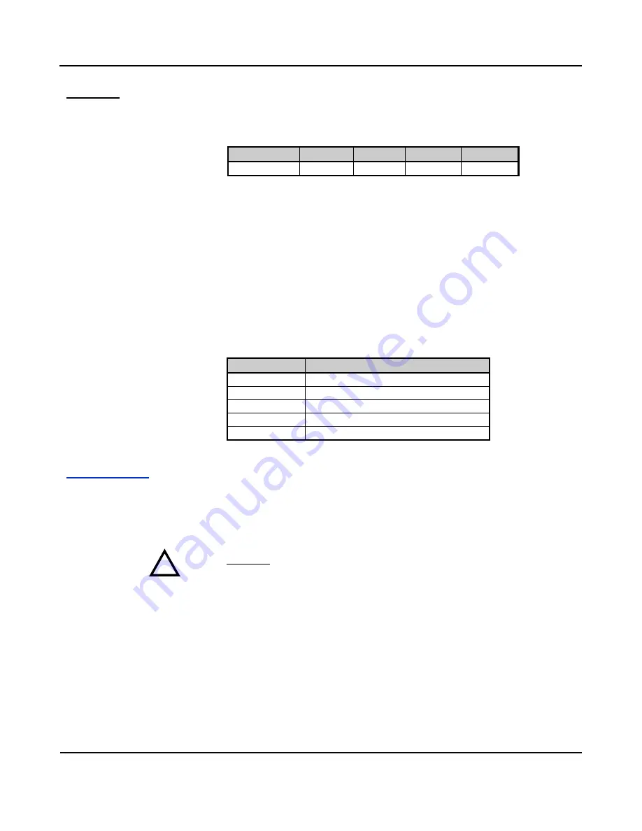
Output Response Time:
The maximum time measured for the output signal to
reach 98% of its transition for a step change in the input while driving current
output into a 250
load with a 24V supply and with the input set to No filter, Low
filter, Medium filter, and High filter.
FILTER
NONE
LOW
MEDIUM
HIGH
DT233-0600
14ms
47ms
136ms
1154ms
Output Power Supply:
Loop powered from 7-32V DC SELV (Safety Extra Low
Voltage), 24mA maximum. The voltage across the output must never exceed 36V,
even with a shorted load. Set this level to provide a minimum of 21mA over-range
current to the load (0.021*R typical), plus 7V across the output terminals, plus any
interim line drop. Reverse polarity protection is inherent as output terminals are
not polarized (the ± output labels of the enclosure label are for reference only).
Output Power Supply Effect:
Less than
0.001% of output span effect per volt DC
of supply change within rated limits for load.
Output Load Resistance Effect:
Less than
0.001% of output span effect for a
100
change in load resistance.
Output Compliance and Load Resistance Equation:
7V minimum is required for
each transmitter channel. Thus, a channel will drive up to 17V to a load with a 24V
loop supply at 20mA of loop current (800
Ω),
assuming negligible line drop.
V
supply
Volts
Max R
load
w/21mA and No IR Line Drop
10V
143
Ω
12V
238
Ω
18V
524
Ω
24V
81
0Ω
32V
119
0Ω
USB Interface
Unit includes a USB mini-B socket for temporary connection to a PC or laptop for set
up and reconfiguration (or optionally to a USB-OTG cable connected to an Android
smartphone or tablet). USB isolation is required when connected to a grounded
input 1 sensor or driver (see note below). During reconfiguration and calibration,
the transmitter receives power from both the USB port and the output loop. Both
power sources must be present to calibrate the unit.
CAUTION:
Do not attempt to connect USB in a hazardous environment. Transmitter
should be set up and configured in a safe environment only.
Data Rate:
USB v1.1 full speed only, at 12Mbps. Up to 32K commands per second.
USB 2.0 compatible.
Transient Protection:
Adds transient voltage protection on USB power & data lines.
Inrush Current Limiting:
Includes series inrush current limiting at USB power.
Cable Length/Connection Distance
: 5.0meters maximum.
Driver:
No special drivers required. Uses the built-in USB Human Interface Device
(HID) drivers of the Windows Operating System (Windows XP or later versions only).
USB Connector:
5-pin, Mini USB B-type socket, HiRose UX60SC-MB-5S8(80).
!

