background image

Model DT233-0600


Dual Two-Wire mV/TC Input Transmitters 


Acromag, Inc. Tel: 248-295-0880  

            - 41 -                                   

http://www.acromag.com  

- 41 - 

https://www.acromag.com 


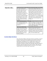
Environmental 

 
These limits represent the 
minimum requirements of the 
applicable standard, but this 
product has typically been tested 
to comply with higher standards 
in some cases. 


Operating Temperature:  -40

C to +80

C (-40

F to +176

F). 

Storage Temperature:  -40

C to +85

C (-40

F to +185

F). 

Relative Humidity:

  5 to 95%, non-condensing. 

Altitude:

  Up to 2000 meters. 

Isolation:

  The Input 1/USB, Input 2, Output 1, and Output 2 circuits are isolated 

from each other for common-mode voltages up to 250VAC, or 354V DC off DC power 
ground, on a continuous basis (will withstand 1500VAC dielectric strength test for 
one minute without breakdown).  Complies with test requirements of UL 61010C-1 

First Edition, August 9, 2002 “UL Standard for Safety for Process Control Equipment” 

for the voltage rating specified. 
Installation Category:  Suitable for installation in a Pollution Degree 2 environment 
with an Installation Category (Over-voltage Category) II rating per IEC 1010-1 (1990). 
Shock & Vibration Immunity:  Random vibration: Designed to comply with VITA 47 
Class V1.  Shall withstand vibration from 5 to 100Hz. with Power Spectral Density 
(PSD) = 0.04g

2

/Hz, for 1 hour per axis.  Testing shall be in accordance with MIL-STD-

810, Method 514, Procedure 1.  Mechanical shock:  Designed to comply with VITA 47 
Class OS1, 20g, 11ms half sine and terminal sawtooth shock pulses.  3 shock pulses in 
each direction along 3 axes (36 shocks, total).  Testing shall be in accordance with 
MIL-STD-810, Method 516, Procedure 1.


Electromagnetic Compatibility (EMC)  
Minimum Immunity per BS EN 61000-6-1: 

1)


Electrostatic Discharge Immunity (ESD), per IEC 61000-4-2. 

2)


Radiated Field Immunity (RFI), per IEC 61000-4-3. 

3)


Electrical Fast Transient Immunity (EFT), per IEC 61000-4-4. 

4)


Surge Immunity, per IEC 61000-4-5. 

5)


Conducted RF Immunity (CRFI), per IEC 61000-4-6. 

This is a Class B Product with Emissions per BS EN 61000-6-3:  

1)


Enclosure Port, per CISPR 16. 

2)


Low Voltage AC Mains Port, per CISPR 14, 16. 


Summary of Contents for DT233-0600

Page 1: ...livoltage Inputs and Passive 4 20mA Loop Powered Outputs USER S MANUAL ACROMAG INCORPORATED Tel 248 295 0880 30765 South Wixom Road email sales acromag com Wixom MI 48393 2417 U S A Copyright 2018 Acromag Inc Printed in the USA Data and specifications are subject to change without notice 8501128E ...

Page 2: ...ns 7 Output Power Connections 8 Earth Ground Connections 11 USB Connections 12 CONFIGURATION SOFTWARE 13 Quick Overview Android Reconfiguration 13 Quick Overview Windows 19 OPERATION STEP BY STEP 21 Connections 21 Thermocouple Millivoltage Versus Temperature Reference Table 22 Setup Communication 23 Configuration 24 Calibration Optional 26 Diagnostics 28 BLOCK DIAGRAM 29 How It Works 29 TROUBLESHO...

Page 3: ...between you and Acromag that this is your responsibility The information of this manual may change without notice Acromag makes no warranty of any kind regarding this material including but not limited to the implied warranties of merchantability and fitness for a particular purpose Further Acromag assumes no responsibility for any errors that may appear in this manual and makes no commitment to u...

Page 4: ...IN rail mounting doubles the density of our TT series This dual transmitter is very flexible in that it may also function as a single transmitter or signal splitter Unit is digitally setup calibrated via wired USB to a Windows based personal computer or USB OTG to an Android tablet or smartphone Adjustable input ranges and adjustable output ranges Transmitter inputs and outputs can be scaled indep...

Page 5: ...ed 4 20mA current loop that is linear to sensor temperature or input voltage Each transmitter output is a passive 2 wire current loop allowing it to transmit 4 20mA over long distances with high noise immunity The inherent live zero 4mA offset of the current loop offers built in output fault detection should an output wire break An extra connection screw at each transmitter output allow it to be o...

Page 6: ...it upward to lift it from the rail while prying the spring clip back with a screwdriver To attach the module to T type DIN rail angle the top of the unit towards the rail and place the top groove of the module over the upper lip of the DIN rail Firmly push the unit downward towards the rail until it snaps into place To remove it from the DIN rail first separate the input terminal blocks from the b...

Page 7: ...are normally separated from input wiring for safety as well as for low noise pickup Important End Stops For hazardous location installations Class I Division 2 or ATEX IECEx Zone 2 it should utilize two end stops like Acromag 1027 222 to help secure modules to the DIN rail not shown Input Connections Sensor input wires are wired directly to transmitter input terminals at the bottom of the module t...

Page 8: ... connections are not polarized The output and designations are for reference only with current normally input to Output and returned via Output current sinking Loop supply voltages should be from 7 32V DC with the minimum voltage level adjusted above 7V transmitter to supply over range current to the loop load plus any transmission line drop Variation in power supply voltage has negligible effect ...

Page 9: ...t loop load and connection wire This makes the 2 wire transmitter flexible in the way it connects to various Receiver devices This passive device does not drive power to the loop and a separate loop power supply is required In most installations the output loop power supply will be local to either the transmitter or local to the remote receiver of the loop Common receiver devices may include the i...

Page 10: ...sent in industrial applications For large 60Hz ripple connect an external 1uF or larger capacitor directly across the load to reduce excess ripple Most modern systems will use high speed acquisition at the load making them more sensitive to noise high frequency noise may be significantly reduced in these applications by placing a 0 1uF or 0 01uF capacitor directly across the load as close to the l...

Page 11: ...rth ground wire connection to the metal housing s ground terminal green screw is usually required using suitable wire per applicable codes As a rule of good practice isolated circuits are normally earth grounded at one point See the Electrical Connections Drawing for Output Power connections and note the traditional position of earth ground for a 2 wire output current loop That is earth ground is ...

Page 12: ...r USB Signal Isolation is Required See Below You may use Acromag model USB ISOLATOR to isolate your USB port or you can optionally use another USB signal isolator that supports USB Full Speed operation 12Mbps Configuration Requires USB and Loop Power This transmitter draws power from both the current loop and from USB during set up IMPORTANT USB logic signals to the unit are referenced to the pote...

Page 13: ... the right of Selected Device and move to the main portion of the app shown in the second screen at left Note Android requires user permission to access external hardware If the Device List displays No Device Permission select the device and when prompted to give permission to access the USB device and select OK If you wish to view a wiring diagram for your transmitter model tap the arrow next to ...

Page 14: ...rform the diagnostic exchange and review the results returned If one or more tests indicate Failed you can also tap the down arrow message below the self test report to access additional information regarding failed tests Optionally you can review an online video tutorial on working with the unit by tapping the Video Tutorial URL line Or if you wish to contact Acromag for assistance you can tap th...

Page 15: ... reset of the transmitter You can tap RESET FACTORY CALIBRATION to get out of trouble if you ever miscalibrate a transmitter this only affects transmitter calibration You can tap RESTORE FACTORY SETTINGS to get out of trouble if you ever misconfigure or miscalibrate a transmitter this affects both transmitter calibration and configuration You can also use this feature to de commission a transmitte...

Page 16: ...MPORTANT The transmitter has already had its input output channels factory calibrated with high precision If you attempt to recalibrate the input or outputs you may degrade its performance if done improperly or by using low grade equipment Consider recalibration carefully The selected input range being calibrated is indicated at the top The software does not use your scaled sub range zero to calib...

Page 17: ...ro 0 of your output range For Full Scale calibration use the output adjustment slider and the coarse and fine adjustment controls to precisely set your output full scale level while precisely monitoring your output signal Be sure to use a meter with an accuracy at least 4x better than the signal you are measuring for best results Note that the output adjustment controls temporarily remove control ...

Page 18: ...value The input type currently set is shown at the top of the screen the input value not the scaled input value is polled Select the Indicator pointer to set your desired indication to Digital value or Graph trend You can specify a polling period to set the interval between polled readings by over typing the value in the Polling Period field Start polling the input by tapping the START POLLING but...

Page 19: ...on A short description of each of these pages follows Communication Setup First Select Connect to Unit Here Select from connected transmitters using the Device scroll field and Open Close communications with them Display the Model Serial Number and Manufacturer of the connected transmitter and report connection Status or reset a connected unit I O Config Test Reconfigure and or Test the Unit Here ...

Page 20: ... Output Instructions button to get started and follow the on screen prompts Input Set the Input Range to calibrate on the I O Config Test page and click Send I O Config before attempting calibration On the Calibration page click the Input Cal Instructions button to begin input calibration When you click the Zero or Full Scale buttons of CALIBRATION Input you will be prompted to apply a current at ...

Page 21: ...r your T C type Refer to the table on the next page for a list of supported thermocouple voltages at specific temperatures After setting the range zero and full scale this way CJC should be returned to ON to enable cold junction compensation when the input is wired using thermocouple wires For best results set the input filter as desired before calibrating an input 2 Connect Output Power each Outp...

Page 22: ...71 27 025 49 116 6 157 5 753 2 101 22 556 700 39 132 29 129 53 112 6 743 6 275 2 431 24 527 760 42 919 31 628 57 870 7 461 6 913 2 854 26 883 800 33 275 61 017 7 950 7 345 3 154 28 455 900 37 326 68 787 9 205 8 449 3 957 32 371 950 39 314 72 603 9 850 9 014 4 387 34 319 1000 41 276 76 373 10 506 9 587 4 834 36 256 1200 48 828 13 228 11 951 6 786 43 846 1300 52 410 14 629 13 159 7 848 47 513 1372 5...

Page 23: ... via a USB hub you can use the Device scroll field to select another unit using the serial number suffix of the Device Model to discern one from another only identical models will be listed Once you have selected a device click Open to open communication with the connected unit After clicking Open the selected unit s Model Serial Number Manufacturer and connection Status will be displayed as shown...

Page 24: ... the Input Type Range for the Channel Input Type refers to the nominal input range wired to TB1 channel 1 or TB3 channel 2 and for DT233 models you may select TC types J K T R S E B N or 100mV Note that nominal input ranges may be rescaled Any nominal input type range you pick here can be rescaled to the output allowing you to use only a portion or sub range of the selected type to drive its curre...

Page 25: ...ge to a smaller sub range For inputs and outputs be careful not to reduce an I O range too much as resolution diminishes in proportion and noise error magnifies each halving of range reduces respective resolution by 1 bit A good rule of thumb to achieve rated performance is to maintain an effective I O resolution of 12 bits or better when scaling I O ranges In the Input Output scaling fields for e...

Page 26: ...ge Additionally make sure you write your selections to the unit by clicking the Send I O Config button of that page Click the Input Cal Instructions button to begin input calibration and enable the Input Zero and Full Scale buttons For the DT233 example click the Input Zero button and you will be prompted to input the minimum value of your selected input range at the appropriate input channel note...

Page 27: ... Next adjust the input signal to drive the output current to precisely 20 000mA Measure this level accurately or performance will be degraded With the output precisely 20 000mA click Output Full Scale of the Calibration Output section to calibrate store the output full scale level Repeat this process for the second output channel CALIBRATION Temp Reference TC Inputs only This section calibrates th...

Page 28: ...Input readings are then displayed in their engineering units Note the simulated lamp next to the button flashes slowly each time it samples the input about once per second Note that input readings will always read down scale if a lead breaks even if you select upscale break detect as break detection only applies to the transmitter output signal Click Stop Polling to stop polling the input channel ...

Page 29: ... 100mV or 1V selecting a normal or reverse acting output selecting a filter level and scaling your input range endpoints to each output range zero full scale endpoints I O scaling can also be done in reverse to produce a reverse acting output signal The maximum over range output is approximately 24mA the minimum under range is 3 6mA Refer to the block diagram to gain a better understanding of how ...

Page 30: ...ith USB connected and config software running Close the current connection with the software then select and re open the transmitter for communication or simply exit the Configuration software and reboot it Cannot Communicate with Transmitter via USB Unit fails to operate or exhibits an output shift Output shifts off range when you connect USB A missing USB Isolator could cause a ground loop betwe...

Page 31: ...istance is too large for the current level Does the output fault LED blink at the higher current Check power voltage level Ideally make sure it is at least 7V plus 0 024 Rload If transmit distance is especially long then it must have added voltage to support the IR drop in the wire Ideally the voltage should also have ample overhead to at least drive the load to 22mA Cannot Measure Input Temperatu...

Page 32: ...nfigure it and calibrate it Boot the configuration software to regain operation The USB port is intended for set up and configuration of the module and it should not be left connected to USB without also booting the USB software Output Fault FLT LED blinks The corresponding output loop voltage is too low to support the loop load current or the load resistance is too high for the loop supply voltag...

Page 33: ...ogram the transmitter USB Isolator USB Isolator Order USB ISOLATOR USB Signal Isolator USB A B Cable 4001 112 Instructions 8500 900 This kit contains a USB isolator and a 1M USB A B cable for connection to a PC This isolator and cable are also included in TT SIP see above USB A B Cable USB A B Cable Order 4001 112 USB A B Cable 4001 112 This is a 1 meter USB A B replacement cable for connection be...

Page 34: ... mobile phone or tablet that support USB It is required to use the Acromag Agility Config Tool App for Android OS reconfiguration of this transmitter Note that the Acromag Agility Config Tool is available free of charge online at the Google Play store End Stops Two End Stops Order 4001 252 Two 1027 222 End Stops for 35 mm DIN Rail mounting For hazardous location installations Class I Division 2 or...

Page 35: ...scale fault detection and channel CJC turned ON Field recalibration of any model will require use of the TTC SIP configuration kit ordered separately see Accessories Inputs Each This unit has separate isolated input channels for thermocouple or DC millivoltage signals at TB1 channel 1 and TB3 channel 2 Input Reference Test Conditions TC Type J with a 10mV minimum span e g Type J 0 to 200 C or 100m...

Page 36: ...ownscale for open sensor lead break fault detection Output limits are scaled I O range dependent and can be from 3 5mA up to 24mA Unit allows you to set your own output limits or you may select Namur Compliant fault limits with a linear operating range from 3 7mA to 20 7mA and break detect set to levels outside of these limits IMPORTANT Calibration should be done with break detection already set a...

Page 37: ...R xGAIN RAW A D INPUT RESOLUTION V 1 000V to 1 000V NONE 1 6554 to 58982 or 1 52428 mV 100mV to 100mV NONE 8 11796 to 53740 or 1 41943 T C J 210 to 760 C 8 095mV to 42 919mV NONE 16 29373 to 50770 or 1 21397 T C K 200 to 1372 C 5 891mV to 54 886mV NONE 16 30297 to 55789 or 1 25492 T C T 260 to 400 C 6 232mV to 20 872mV NONE 32 27540 to 50277 or 1 22736 T C R 50 C to 1768 C 0 226mV to 21 101mV NONE...

Page 38: ...ges Relative accuracy varies with calibrated input and output span and scaling Accuracy includes the combined effects of repeatability terminal point conformity and linearization but does not include sensor error Output Ripple Noise Less than 0 1 of output span Note High Speed Acquisition Additional filtering at the loop load is recommended for sensitive applications with high speed acquisition ra...

Page 39: ...ct Less than 0 001 of output span effect for a 100 change in load resistance Output Compliance and Load Resistance Equation 7V minimum is required for each transmitter channel Thus a channel will drive up to 17V to a load with a 24V loop supply at 20mA of loop current 800Ω assuming negligible line drop Vsupply Volts Max Rload w 21mA and No IR Line Drop 10V 143Ω 12V 238Ω 18V 524Ω 24V 810Ω 32V 1190Ω...

Page 40: ...mmended when connecting to a PC Otherwise in the absence of USB isolation and when connected to a grounded input 1 sensor a battery powered laptop could be used to connect to the unit as the laptop does not normally connect to earth ground Enclosure Physical General purpose plastic enclosure for mounting on 35mm T type DIN rail Dimensions Width 17 5mm 0 69 inches Length 114 5mm 4 51 inches Depth 9...

Page 41: ...tion Category Suitable for installation in a Pollution Degree 2 environment with an Installation Category Over voltage Category II rating per IEC 1010 1 1990 Shock Vibration Immunity Random vibration Designed to comply with VITA 47 Class V1 Shall withstand vibration from 5 to 100Hz with Power Spectral Density PSD 0 04g2 Hz for 1 hour per axis Testing shall be in accordance with MIL STD 810 Method ...

Page 42: ...ion MTBF Mean Time Between Failure MTBF in hours using MIL HDBK 217F FN2 Per MIL HDBK 217 Ground Benign Controlled GBGC Temperature MTBF Hours MTBF Years Failure Rate FIT1 25 C 1 197 365 hrs 136 7 years 835 2 40 C 798 569 hrs 91 2 years 1 252 2 1 Note FIT is Failures in 109 hours Configuration Controls Software Configuration Only via USB Windows or USB OTG Android Agility This dual transmitter mod...

Page 43: ...for this document Release Date Version EGR DOC Description of Revision 11 DEC 2018 A BC MJO Updated Preliminary Review Version A 16 JUN 2020 B BC ARP MTBF information and EMC Directive updated 15 SEP 2020 C CAP ARP Added cULus ATEX IECEx and FCC approvals 28 JAN 2022 D CAP AMM Added Altitude Up to 2000 meters Environmental Section 11 OCT 2022 E BC Removed remnant mention of voltage current inputs ...

Reviews: