Model DT233-0600
Dual Two-Wire mV/TC Input Transmitters
Acromag, Inc. Tel: 248-295-0880
- 24 -
http://www.acromag.com
- 24 -
https://www.acromag.com
Configuration
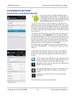
The field settings shown refer the module’s
current
configuration and the only way to preserve any
changes is to either write them to the device via
[Send
I/O Config]
, or by saving them to a file by clicking
“
F
ile”
in the upper left-hand corner of the screen.
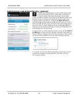
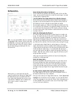
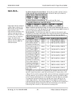
If you click the “Configuration” tab
to reconfigure the connected
unit, the software retrieves
the unit’s current configuration and
displays it as shown at left.
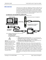
Note that DT200 transmitters receive power from their USB
connection which allows you to conveniently demonstrate the
configuration software without also having to power the output
loops, unless you plan to write your configuration to the unit or
test its operation.
IMPORTANT:
DT models have three modes of operation: Dual
Transmitter, Single Transmitter, and Signal Splitter. Your
Configuration screen will vary slightly with the Operating Mode
selected.
If you make any changes to this screen, but do not Send your
changes to the unit, you can always
retrieve the module’s
stored configuration by clicking the
[Get I/O Config]
button at
the top of this screen.
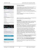
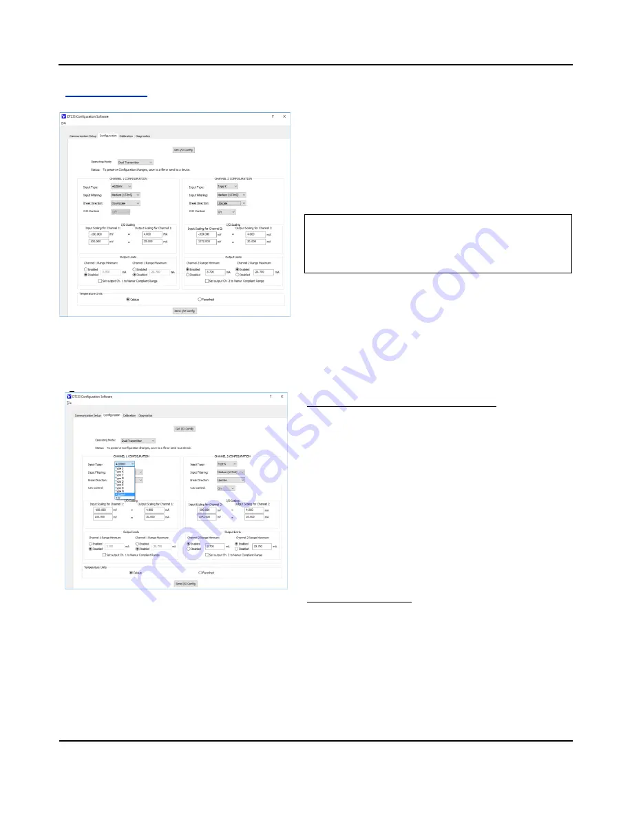
Select the Input Type/Range for the Channel
…
Input Type refers to the nominal input range wired to TB1
(channel 1) or TB3 (channel 2) and for DT233 models, you may
select TC types J, K, T, R, S, E, B, N, or ±100mV. Note that
nominal input ranges may be rescaled.
Any nominal input type/range you pick here can be rescaled to
the output, allowing you to use only a portion or sub-range of
the selected type to drive its current output, as desired. Keep in
mind that your resolution will decrease proportionally as you
rescale the input signal to a smaller sub-range. Each halving of
the nominal range will reduce its resolution by 1 bit. This can
also magnify error, especially noticeable for very small input
ranges (less than 12 bits) which degrade the signal-to-noise ratio
of the input and resolution of the analog-to-digital conversion.
Select the Input Filtering
…
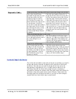
You may select the level of digital filtering to apply to the input
channel as Low, Medium, High, or None (No digital filtering).
I/O response time varies with input filter selection and typical
times are indicated in parenthesis next to filter selection.
Higher filter levels result in lower average noise, but with a
slower I/O response time (see Specifications for detail).
To accomplish reconfiguration, you must have loop power
connected to each output loop of this dual transmitter.
You will not be able to calibrate a unit or test it without
loop power also applied to at least one output.


