Model DT233-0600
Dual Two-Wire mV/TC Input Transmitters
Acromag, Inc. Tel: 248-295-0880
- 8 -
http://www.acromag.com
- 8 -
https://www.acromag.com
Output/Power Connections
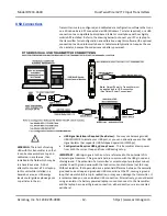
The transmitter output is
passive. It modulates loop
current relative to its input and
does not drive power to the
load (a separate external loop
power supply is required to
excite the current loop).
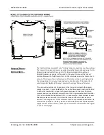
This dual transmitter has two isolated ANSI/ISA Type 2 outputs in which their
channel
’s power and output signal share the same two
leads, and each transmitter
output has a “floating” connection with respect to earth ground. Connect a DC
power supply and load in series in each of the two-wire output loops as shown in
the drawings that follow.
•
Passive output connections are not polarized
. The and
–
designations
are for reference only with current normally input to and returned via
Output- (current sinking).
•
Loop supply voltages should be from 7-32V DC
with the minimum voltage level
adjusted above 7V (transmitter) to supply over-range current to the loop load,
plus any transmission line drop.
•
Variation in power supply voltage has negligible effect on transmitter
accuracy
between the 7V minimum required (transmitter only) and 32V
maximum allowed.
•
Variation in load resistance has negligible effect on output accuracy
if the loop
supply voltage level is set correctly for the load resistance.
•
Note the traditional placement of earth ground in a current loop.
Output
Earth ground is normally applied at the loop power supply minus terminal.
Each 2-wire transmitter output varies off this ground by the voltage drop in the
load resistance and lead-wire of the loop.


