IntelliPack Series 892M/894M Computation Transmitter User's Manual DC Voltage/Current Input
___________________________________________________________________________________________
- 11 -
serves as an isolated interface converter between EIA232
and the IntelliPack’s SPI port.
Baud Rate (EIA232):
19.2K baud.
SOFTWARE CONFIGURATION
Units are fully reprogrammable via our user-friendly Windows
95/98
or NT
IntelliPack Configuration Program (Model 5030-
881). Programmable attributes for this model are given below. A
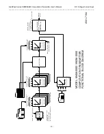
cable (5030-902) and converter (5030-913) are required to
complete the interface (Software Interface Package 800C-SIP).
See Drawing 4501-643. Additional information can be found in
the IntelliPack Transmitter Configuration Manual (8500-570).
Input Configuration
Input - Range (Each Input):
The transmitter can be configured
to accept any one of the five input range types shown below.
However, a short jumper wire must be installed between the
input “I+” and “V+” terminals to utilize current input. Input
range volts and milliamperes can be scaled to engineering
units per your application (see Transmitter Configuration).
Voltage:
0 to 10V DC, 0 to 5V DC.
Current (Jumper Required):
0-20mA, 4-20mA, or 0-1mA
DC.
Input Calibration (Each Input, Each Range):
The IntelliPack
Configuration Software is used to calibrate available input
ranges at each input channel of this module.
Output Configuration
Output - Range:
Analog output can be configured for one of five
ranges of current or voltage. For voltage output, a jumper
must also be installed between the output “I+” and “JMP”
terminals (remove this jumper for current output).
Voltage (Jumper Required):
0 to 10V DC, 0 to 5V DC.
Current:
0 to 20mA DC, 4 to 20mA DC, or 0 to 1mA DC.
Output - Mode:
Select a Normal Acting (ascending), or Reverse
Acting (descending) output response.
Output Calibration
: The configuration software can be used to
calibrate the output conditioning circuit of this module.
Transmitter Configuration
Transmitter - Scaling:
Scaled values must be entered for each
input to translate the nominal zero and full-scale input range
endpoint values indicated, to engineering units per the
requirements of your application. Up to 8 characters may be
used to specify constants and scientific notation is supported.
Up to 6 characters may be used to describe the engineering
units of the scaled input and output values. For example, a
4-20mA input signal range may be scaled to 0 to 5000 GPM.
The equation only operates on the equivalent scaled input
values. The computed output value is also scaled to nominal
zero and full-scale output range endpoint values for the
voltage or current output range selected.
Transmitter - Equation:
Up to 200 characters may be used to
specify an output equation that is the mathematical
combination of up to four inputs (894M), or two inputs
(892M). A free-
form equation is entered in “in-fix” notation
that uses floating-point constants, scaled input channel
variables, standard operators (+, -, *, /, ( )), plus square root
(SQR( )), absolute value (ABS( )), minimum select (MIN( )),
maximum select (MAX( )), exponential (EXP( )), natural
logarithm (LN( )), logarithm base 10 (LOG10( )), power
(POWER( )), sine (SIN( )), cosine (COS( )), tangent (TAN( )),
arc sine (ASIN( )), arc cosine (ACOS( )), and arc tangent
(ATAN( )). Support for IF-THEN-ELSE, plus AND & OR, >,
>=, <, <=, =, <> constructs are included.
Constants are single precision floating-point values (scientific
notation supported) and are limited to 8 characters. The
computed output is then scaled to nominal output range
endpoints.
Transmitter - Show Simulator:
The Show Simulator function is
used to test your equation and ensure that a correct output
response within range is produced, without having to drive
the inputs with real world signals. Slide controls are provided
to vary simulated input signals (click and drag with your
mouse). Fine control of the slide controls is also possible via
your arrow keys. Error checking in this area is limited and it
is up to the user to verify correct formulation for all possible
conditions of input and output. As such, use of the Show
Simulator function is highly recommended for critical control
applications.
Visual Over-Range Indicator:
A yellow LED for each channel
provides visual status indication of when the input signal is
out of range (LED is ON for over-range).
Output HOLD Function:
A TTL or open collector/drain signal
(5V logic) may be wired directly to the HOLD terminal of the
module to hold the transmitter’s output at the last value.
HOLD is asserted low (with respect to COM) and pulled-up
internally. The HOLD circuit is part of the input circuit and
isolated from the output circuit.
WARNING:
Input return (RTN) and common (COM) are not
equivalent potentials and should never be tied together.
Make sure that common is not inadvertently tied to ground
which may connect to input return.
Other IntelliPack Configuration Software Capabilities
In addition to configuring all features of the module described
above, the IntelliPack Configuration Software includes additional
capabilities for testing and control of the module as follows:
•
Monitors the input and output signal values and allows
polling to be turned on or off.
•
Provides a “Show Simulator” function to simulate input
variations and test the programmed equation.
•
Allows a configuration to be uploaded or downloaded to/from
the module. Also provides a means to rewrite a module’s
firmware if the microcontroller is replaced or a module’s
functionality is updated.
•
Provides controls to separately calibrate the input and output
stages and restore the original factory input or output
calibration in case of error.
•
Provides a control to reset a module.
•
Provides a control to adjust a transmitter’s output signal
independent of the input signals (includes timed override).
•
Allows optional user documentation information to be written
to the module. Documentation fields are provided for tag
number, comment, configured by, location, and identification
information. This information can also be uploaded from the
module and printed via this software.
•
Allows a module’s complete configuration to be printed in an
easy to read, two-page form, including user documentation.
•
Includes on-line help and context (field) sensitive help
functions.
For additional information on the IntelliPack Configuration
Software, refer to the Transmitter Configuration Manual
8500-570.

