IntelliPack Series 892M/894M Computation Transmitter User's Manual DC Voltage/Current Input
___________________________________________________________________________________________
- 4 -
IntelliPack Serial Port Adapter (Model 5030-913)
This adapter serves as an isolated interface converter
between the EIA232 serial port of the host computer and the
Serial Peripheral Interface (SPI) port of the IntelliPack module. It
is used in conjunction with the Acromag IntelliPack Configuration
Software to program and configure the modules. This adapter
requires no user adjustment, no external power, and operates
transparent to the user. It receives its power from the IntelliPack
module. The adapter has a DB9S connector that mates to the
common DB9P serial port connector of a host computer. The
adapter also has a 6-wire
RJ11 phone jack to connect to the
IntelliPack alarm module via a separate interconnecting cable
(described below). Refer to Drawing 4501-635 for computer to
IntelliPack connection details.
IntelliPack Cable (Model 5030-902)
This 6-wire cable is used to connect the SPI port of the
IntelliPack Serial Port Adapter to the IntelliPack. This cable
carries the SPI data and clock signals, reset signal, and +5V
power and ground signals. The cable is 7 feet long and has a 6-
wire RJ11 plug at both ends which snap into jacks on the Serial
Port Adapter and the IntelliPack module.
IntelliPack Software Interface Package (Model 800C-SIP)
The IntelliPack Software Interface Package combines the
Configuration Software (5030-881), Alarm Configuration Manual
(8500-563), Transmitter Configuration Manual (8500-570), Serial
Port Adapter (5030-913), and Cable (5030-902), into a complete
kit for interfacing with IntelliPack Alarms and Transmitters.
2.0 PREPARATION FOR USE
UNPACKING AND INSPECTION
Upon receipt of this product, inspect the shipping carton for
evidence of mishandling during transit. If the shipping carton is
badly damaged or water stained, request that the carrier's agent
be present when the carton is opened. If the carrier's agent is
absent when the carton is opened and the contents of the carton
are damaged, keep the carton and packing material for the
agent's inspection. For repairs to a product damaged in
shipment, refer to the Acromag Service Policy to obtain return
instructions. It is suggested that salvageable shipping cartons
and packing material be saved for future use in the event the
product must be shipped.
This module is physically protected
with packing material and electrically
protected with an anti-static bag during
shipment. However, it is
recommended that the module be
visually inspected for evidence of
mishandling prior to applying power.
This circuit utilizes static sensitive
components and should only be
handled at a static-safe workstation.
INSTALLATION
The transmitter module is packaged in a general purpose
plastic enclosure. Use an auxiliary enclosure to protect the unit in
unfavorable environments or vulnerable locations, or to maintain
conformance to applicable safety standards. Stay within the
specified operating temperature range. As shipped from the
factory, the unit is factory calibrated for all valid input ranges and
has the default configuration shown in Table 3 below.
WARNING:
Applicable IEC Safety Standards may require that
this device be mounted within an approved metal enclosure or
sub-system, particularly for applications with voltages greater
than or equal to 75VDC or 50VAC.
Table 3: 89XM Default Factory Configuration
PARAMETER
CONFIGURATION/CALIBRATION
Input 1 Range
4
0 to 10V DC
4
Input 2 Range
4
0 to 10V DC
4
Input 3 & 4 Range
1,4
0 to 10V DC, each channel
1,4
Output Range
2
0 to 10V DC (Jumper Installed)
2
Output Mode
Normal Acting (Ascending Signal)
Input 1 Scaling
0-10V DC = 0-100
Input 2 Scaling
0-10V DC = 0-100
Input 3 Scaling
0-10V DC = 0-100
Input 4 Scaling
0-10V DC = 0-100
Output Scaling
0-100 = 0-10VDC
Equation
3
(892M-0500)
Output = A
Equation
3
(894M-0500)
Output = A
Notes (Table 3):
1. Channels 3 & 4 of the Model 894M-0500 must be configured
for the same input signal type and range, but they may be
scaled differently.
2. An external jumper is installed between the output “I+” and
“JMP” terminals for voltage output. You must remove this
jumper to use current output ranges.
3. Variables A, B, C, & D are used in the output equation to
represent input channels 1, 2, 3, & 4, respectively.
4. For process current input ranges, a short jumper wire must be
inserted between the input “I+” and “V+” terminals (not
included). This jumper is removed for voltage input ranges.
Your application may differ from the default configuration and
will require that the transmitter be reconfigured to suit your needs.
This is accomplished with Acromag’s user-friendly Windows
95/98
or NT
Configuration Program and Serial Port Adapter. It
is usually more convenient to configure the module prior to field
installation. See the Transmitter Configuration Manual
(8500-570) for additional instructions.
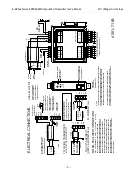
Jumper Installation (Current Input)
For process current input, a short jumper wire must be
installed between the input “I+” and “V+” terminals. This jumper
is not included from the factory. Remove this jumper for voltage
input applications. Refer to the Electrical Connections Drawing
4501-719.


