SERIES IOS-320 I/O SERVER MODULE 12-BIT HIGH DENSITY ANALOG INPUT BOARD
__________________________________________________________________________________________
- 10 -
Acromag, Inc. Tel:248-295-0310 Fax:248-624-9234 Email:solutions@acromag.com http://www.acromag.com
(1)
CALLO
Count
m
Ideal_Zero
-
Gain)
*
CALLO
(Volt
al
Count_Actu
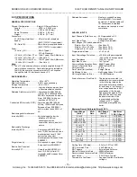
The following equation (1) is used to correct the actual ADC
data (i.e. the uncorrected bit count read from the ADC) making
use of the calibration voltages and range constants.
where, "m" represents the actual slope of the transfer
characteristic as defined in equation 2:
m = Gain
VoltCALHI VoltCALLO
CountCALHI CountCALLO
(2)
Gain
=
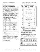
The Programmable Gain
Amplifier Setting Used (See
Table 3.4)
VoltCALHI
=
High Calibration Voltage
(See Table 3.4)
VoltCALLO
=
Low Calibration Voltage
(See Table 3.4)
CountCALHI
=
Actual ADC Data Read With
High Calibration Voltage Applied
CountCALLO
=
Actual ADC Data Read With Low
Calibration Voltage Applied
Ideal_Volt_Span
=
Ideal ADC Voltage Span
(See Table 3.5)
Count_Actual
=
Actual Uncorrected ADC Data
For Input Being Measured
Ideal_Zero
=
Ideal ADC Input For “Zero” (See
Table 3.5)
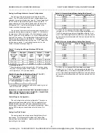
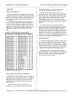
Table 3.5: Ideal Voltage Span and Zero For Input Ranges
Input Range
(Volts)
PGA
Gain
ADC
Range
(Volts)
"Ideal_Volt
_Span"
(Volts)
"Ideal_
Zero"
(Volts)
-5 to +5
1
-5 to +5
10.0000
-5.0000
-2.5 to +2.5
2
"
"
"
-1.25 to +1.25
4
"
"
"
-0.625 to
+0.625
8
"
"
"
-10 to +10
1
-10 to +10
20.0000
-10.0000
-5 to +5
2
"
"
"
-2.5 to +2.5
4
"
"
"
-1.25 to +1.25
8
"
"
"
0 to +10
1
0 to +10
10.0000
0.0000
0 to +5
2
"
"
"
0 to +2.5
4
"
"
"
0 to +1.25
8
"
"
"
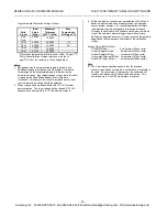
The calibration parameters (CountCALHI and CountCALLO)
for each active input range should be determined at startup and
updated periodically (e.g. once an hour, or more often if ambient
temperatures change) to obtain the best accuracy. Note that
several readings (e.g. 16) of the calibration parameters should be
taken via the ADC and averaged to reduce the measurement
uncertainty.
Calibration Programming Example 1
Assume that the input range is -10 to +10 volts. Channel 0 is
connected differentially, and corrected input channel data is
desired. From Tables 3.4 & 3.5, several calibration parameters
can be determined:
Gain = 1 (From Table 3.4)
VoltCALHI = 4.9000 volts (CAL0; From Table 3.4)
VoltCALLO = 0.0000 volts (Auto Zero; From Table 3.4)
Ideal_Volt_Span = 20.0000 volts (From Table 3.5)
Ideal_Zero = -10.0000 volts (From Table 3.5)
The calibration parameters (CountCALHI and CountCALLO)
remain to be determined before uncorrected input channel data
can be taken and corrected.
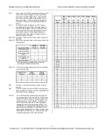
1. To prepare to measure CountCALLO, write to the Control
Register (@Base + 00H) to setup the auto zero acquisition
mode and PGA gain = 1 by writing 0300H. Note that "not
used" and "don't care" bits are set to zero.
2. Delay to allow for input settling.
3. Execute ADC Convert Command (@Base + 10H).
4. Execute Read ADC Data Command (@Base + 20H). Note
that the 12-bit data is left-justified within the 16-bit word.
5. Repeat steps 3 and 4 several times (e.g. 16) and take the
average of the ADC results. Save this number as
CountCALLO.
6. To prepare to measure CountCALHI, write to the Control
Register (@Base + 00H) to setup the CAL0 acquisition mode
and PGA gain = 1 by writing 0014H. Note that "not used" bits
are set to zero.
7. Delay to allow for input settling.
8. Execute ADC Convert Command (@Base + 10H).
9. Execute Read ADC Data Command (@Base + 20H). Note
that the 12-bit data is left-justified within the 16-bit word.
10. Repeat steps 8 and 9 several times (e.g. 16) and take the
average of the ADC results. Save this number as
CountCALHI.
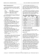
11. Calculate m = actual_slope from equation 2, since all
parameters are known.
It is now possible to correct input channel data from any input
channel using the same input range (i.e. -10 to +10 volts with
a PGA gain = 1). Repeat steps 1-11 periodically to re-
measure the calibration parameters (CountCALHI and
CountCALLO) as required.
12. To prepare to measure channel 0 differentially, write to the
Control Register (@Base + 00H) to setup the differential input
channel 0 acquisition mode and PGA gain = 1 by writing
0000H. Note that "not used" bits are set to zero.
13. Delay to allow for input settling.
14. Execute ADC Convert Command (@Base + 10H).
15. Execute Read ADC Data Command (@Base + 20H). Note
that the 12-bit data is left-justified within the 16-bit word. This
data represents the uncorrected "Count_Actual" term in
equation 1. Since all parameters on the right hand side of
equation 1 are known. Calculate the calibrated value
"Corrected_Count". This is the desired, corrected value for
input channel 0.
16. Repeat steps 12-15 to re-measure channel zero's data as
desired.
*
_Span
Ideal_Volt
m
4096
=
Count
Corrected_

