SERIES IOS-320 I/O SERVER MODULE 12-BIT HIGH DENSITY ANALOG INPUT BOARD
__________________________________________________________________________________________
- 14 -
Acromag, Inc. Tel:248-295-0310 Fax:248-624-9234 Email:solutions@acromag.com http://www.acromag.com
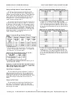
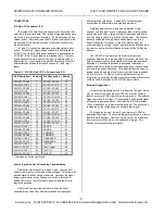
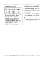
Programmable Calibration Voltages follow:
Calib.
Signal
Ideal
Value
(Volts)
Maximum
Tolerance
@25
°
C (Volts)
Max
Temperature
Drift (ppm/
°
C)
Auto
Zero
0.0000
0.0002
0
CAL0
4.9000
0.0005
15
CAL1
2.4500
0.0005
20*
CAL2
1.2250
0.0004
"
CAL3
0.6125
0.0002
"
* Worst case temperature drift is the sum of the 15 ppm/oC
drift of the calibration voltage reference, plus the 5
ppm/oC drift of the resistors in the voltage divider.
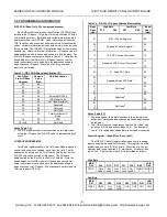
Notes:
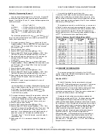
2. Range assumes the programmable gain is equal to one.
Additional ranges are created with other gains. Divide the
listed range by the programmable gain to determine the
actual input range. Input signal ranges may actually fall short
of reaching the specified endpoints due to hardware
limitations. For example, if an input may reach zero volts or
less, a bipolar input range should be selected.
3. These ranges can only be achieved with 15 Volt external
power supplies. The input ranges will be clipped if 12 Volt
supplies are used, typically to 9 Volt maximum inputs.
4. Follow the input connection recommendations of Section 2,
because input noise and non-ideal grounds can degrade
overall system accuracy. For critical applications multiple
input samples can be averaged to improve performance.
Accuracy is specified for the software conversion command.
Use of the external hardware trigger input with software
polling may degrade accuracy. Accuracy versus temperature
depends on the temperature coefficient of the calibration
voltage.
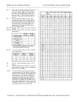
Access Times (8MHz Clock):
ID PROM Read......................0 wait states (250ns cycle).
Control Register Read............0 wait states (250ns cycle).
Control Register Write............1 wait state (375ns cycle).
Conversion Request (Write)...1 wait states (375ns cycle).
Read ADC Data (Note 5)........2 wait states (500ns cycle).
Note
:
5. The 2 wait states specified assume that the previous
conversion has been completed, and that data is available to
be read. If a conversion is in progress, the command will
institute wait states until the data can be delivered. This
could take up to 4.5uS (32 wait states), maximum.

