SERIES IOS-320 I/O SERVER MODULE 12-BIT HIGH DENSITY ANALOG INPUT BOARD
__________________________________________________________________________________________
- 2 -
Acromag, Inc. Tel:248-295-0310 Fax:248-624-9234 Email:solutions@acromag.com http://www.acromag.com
The information contained in this manual is subject to change
without notice. Acromag, Inc. makes no warranty of any kind with
regard to this material, including, but not limited to, the implied
warranties of merchantability and fitness for a particular purpose.
Further, Acromag, Inc. assumes no responsibility for any errors
that may appear in this manual and makes no commitment to
update, or keep current, the information contained in this manual.
No part of this manual may be copied or reproduced in any form,
without the prior written consent of Acromag, Inc.
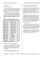
Table of Contents
Page
1.0 GENERAL INFORMATION
……………………………….
2
KEY ANALOG INPUT FEATURES………………………
2
I/O SERVER MODULE INTERFACE FEATURES…….
3
I/O SERVER MODULE SOFTWARE…………………...
3
2.0 PREPARATION FOR USE
………………………………..
3
UNPACKING AND INSPECTION………………………..
3
BOARD CONFIGURATION……………………………….
3
Default Hardware Jumper Configuration……………..
3
Analog Input Range Hardware Jumper Configuration
4
Control Register Configuration………………………...
4
Analog Input Data Format……………………………...
4
CONNECTORS…………………………………………….
4
IOS Field Connector (P2)…………………………….
4
Analog Input Noise and Grounding C
onsiderations…
5
External Trigger Input…………………………………..
5
3.0
PROGRAMMING INFORMATION
……………………….
5
ID SPACE…………………………………………………..
5
I/O SPACE ADDRESS MAP……………………………...
6
Control Register…………………………………………
6
ADC Convert Command………………………………..
7
Read ADC Data…………………………………………
7
PROGRAMMING.CONSIDERATIONS………………….
8
Using the Separate ADC Convert & Read Command
8
Using External Conversion Triggers…………………..
8
USE OF CALIBRATION SIGNALS………………………
8
Uncalibrated Performance…………………………….
8
Calibrated Performance……………………………….
9
4.0
THEORY OF OPERATION
……………………………….
11
ANALOG INPUTS………………………………………….
11
IOS-
320……………………………………….
11
5.0
SERVICE AND REPAIR
…………………………………..
12
SERVICE AND REPAIR ASSISTANCE…………………
12
PRELIMINARY SERVICE PROCEDURE……………….
12
WHERE TO GET HELP…………………………………..
12
6.0
SPECIFICATIONS
…………………………………………
12
GENE
RAL SPECIFICATIONS……………………………
12
ENVIRONMENTAL……….………………………………..
12
ANALOG INPUTS………………………………………….
13
DRAWINGS
Page
IOS-
320 JUMPER LOCATIONS……………
14
IOS-
320 BLOCK DIAGRAM………………..
15
ANALOG INPUT CONNECTION DIAGRAM.
15
IMPORTANT SAFETY CONSIDERATIONS
It is very important for the user to consider the possible adverse
effects of power, wiring, component, sensor, or software failures
in designing any type of control or monitoring system. This is
especially important where economic property loss or human life
is involved. It is important that the user employ satisfactory
overall system design. It is agreed between the Buyer and
Acromag, that this is the Buyer's responsibility.
1.0 GENERAL INFORMATION
The I/O Server Module IOS-320 is a 12-bit, high-density,
single-size IOS analog input board with the capability to monitor
20 differential or 40 single-ended analog input channels. The
IOS-320 utilizes state of the art Surface Mounted Technology
(SMT) to achieve its high channel density. It offers a variety of
features which make it an ideal choice for many industrial and
scientific applications as described below.
Important Note:
The following IOS model are accessories to the
IOS Server Models: IOS-7200, IOS-7200-WIN, IOS-7400, and
IOS-7400-WIN; which are cULus Listed. This equipment is
suitable for use in Class I, Division 2, Groups A, B, C, and D or
non-hazardous locations only.
Model
Operating Temperature Range
IOS-320
-40 to 85
o
C
KEY ANALOG INPUT FEATURES
High Channel Count -
Monitors up to 20 differential, or 40
single-ended analog inputs (acquisition mode and channels
are selected via a programmable control register). Up to
four units may be mounted on a carrier board providing up to
80 differential inputs, or 160 single-ended inputs in a single
system slot.
12-bit Accuracy -
Contains an enhanced, 12-bit, successive
approximation Analog to Digital Converter (ADC) with a
4.5uS conversion time.
High Speed -
The recommended maximum system
throughput rate is 100KHz.
Multiple Input Range
–
A Hardware DIP switch allows for
selectable ranges for both bipolar and unipolar voltage
inputs: -5 to +5V, -10 to +10V, and 0 to +10V.
Programmable Gain -
Gains of 1, 2, 4, and 8 are
programmable via the control register.
Software/Hardware Trigger -
Input acquisition can be
triggered via software, or by an external hardware input for
synchronization to external events.
Precision References -
On-board, high-precision voltage
references provide the means for accurate and reliable
software calibration of the module.
Conduction Cooled Module
- I/O modules employ
advanced thermal technologies. A thermal pad and module
cover wicks heat away from the module and transfers the
energy to a heat spreading friction plate. Heat moves to the
enclosure walls where it is dissipated by the external cooling
fins.

