SERIES IOS-320 I/O SERVER MODULE 12-BIT HIGH DENSITY ANALOG INPUT BOARD
__________________________________________________________________________________________
- 5 -
Acromag, Inc. Tel:248-295-0310 Fax:248-624-9234 Email:solutions@acromag.com http://www.acromag.com
CONNECTORS
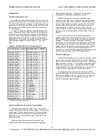
IOS Field I/O Connector (P2)
P2 provides the field I/O interface connector for mating IOS
modules to the carrier board. The field and logic side connectors
are keyed to avoid incorrect assembly. P2 pin assignments are
unique to each IOS model (see Table 2.5) and correspond to the
pin numbers of the front-panel, field I/O interface connector on
the carrier board).
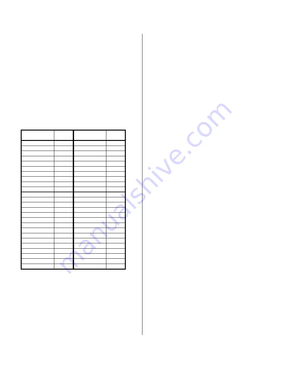
In Table 2.5, channel designations are abbreviated to save
space. For example, single-ended channel 0 is abbreviated as
"SCH00"; the +input for differential channel 0 is abbreviated as
"+DCH00". Both of these labels are attached to pin 1, but only
one applies according to whether the input is single-ended or
differential (i.e. if your inputs are applied differentially, follow the
differential channel labeling for each channel's + and - input
leads).
Table 2.5: IOS-320 Field I/O Pin Connections (P2)
* Indicates an Active-Low Signal
Analog Input Noise and Grounding Considerations
Differential inputs require two leads (+ and -) per channel,
and provide rejection of common mode voltages. This allows the
desired signal to be accurately measured. However, the signal
being measured cannot be floating--it must be referenced to
analog common on the IOS module and be within the normal
input voltage range.
Differential inputs are the best choice when the input
channels are sourced from different locations having slightly
different ground references. See page 14 for analog input
connections for differential and single-ended inputs.
Single-ended inputs only require a single lead (+) per
channel, with a shared "sense" (reference) lead for all channels,
and can be used when a large number of input channels come
from the same location (e.g. printed circuit board). The channel
density doubles when using single-ended inputs, and this a
powerful incentive for their use. However, caution must be
exercised since the single "sense" lead references all channels to
the same common which will induce noise and offset if they are
different.
The IOS-320 is non-isolated, since there is electrical
continuity between the logic and field I/O grounds. As such, the
field I/O connections are not isolated from the carrier board and
backplane. Care should be taken in designing installations
without isolation to avoid noise pickup and ground loops caused
by multiple ground connections. This is particularly important for
analog inputs when a high level of accuracy/resolution is needed
(12-bits or more). Contact your Acromag representative for
information on our many isolated signal conditioning products that
could be used to interface to the IOS-320 input module.
External Trigger Input
The external trigger signal on P2 is an active-low input which
may be used for synchronizing the ADC conversion of analog
inputs from several IOS modules to external events. The external
trigger must be a 5 Volt logic, TTL-compatible, debounced signal
referenced to analog common. Note that the IOS-320 provides
125ns of debounce on the external trigger input. The conversion
is triggered on the falling edge of a normally high signal.
The trigger pulse must be low for a minimum of 250nS to
guarantee acquisition. The external trigger may remain low for an
indefinite period of time. However, it must return to a high state
for a minimum of 250nS prior to a subsequent trigger. See
Section 3 for programming information.
Pin Description
Number
Pin Description
Numbe
r
SCH00/+DCH00
1
SCH32/-DCH12
26
SCH20/-DCH00
2
SCH13/+DCH13
27
SCH01/+DCH01
3
SCH33/-DCH13
28
SCH21/-DCH01
4
SCH14/+DCH14
29
SCH02/+DCH02
5
SCH34/-DCH14
30
SCH22/-DCH02
6
SCH15/+DCH15
31
SCH03/+DCH03
7
SCH35/-DCH15
32
SCH23/-DCH03
8
SCH16/+DCH16
33
SCH04/+DCH04
9
SCH36/-DCH16
34
SCH24/-DCH04
10
SCH17/+DCH17
35
SCH05/+DCH05
11
SCH37/-DCH17
36
SCH25/-DCH05
12
SCH18/+DCH18
37
SCH06/+DCH06
13
SCH38/-DCH18
38
SCH26/-DCH06
14
SCH19/+DCH19
39
SCH07/+DCH07
15
SCH39/-DCH19
40
SCH27/-DCH07
16
SENSE
41
SCH08/+DCH08
17
SENSE
42
SCH28/-DCH08
18
COMMON
43
SCH09/+DCH09
19
COMMON
44
SCH29/-DCH09
20
RESERVED
45
SCH10/+DCH10
21
RESERVED
46
SCH30/-DCH10
22
-15V DC
47
SCH11/+DCH11
23
*Ext Trigger
48
SCH31/-DCH11
24
+15V DC
49
SCH12/+DCH12
25
SHIELD
50

